Contents 1.1 1.2 1.3 1.4 1.5 1.6 1.7 General safety instructions Manufacturer liability Appliance purpose Disposal Identification plate This user manual How to read the user manual 2 Description 2.1 2.2 2.3 2.4 2.5 General Description Cooking hob Control panel Other parts Available accessories 3 Use 3.1 3.2 3.3 3.4 3.5 3.6 3.
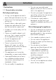
Instructions 1 Instructions 1.1 General safety instructions Risk of personal injury • During use the appliance and its accessible parts become very hot. • Never touch the heating elements during use. • Keep children under eight years of age at a safe distance if they are not constantly supervised. • Children must never play with the appliance. • Never rest metallic objects such as knives, forks, spoons and lids on the appliance during use. • Switch the appliance off immediately after use.
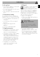
For this appliance 1.4 Disposal • Ensure that the appliance is switched off before replacing the bulb. • Do not rest any weight or sit on the open door of the appliance. • Take care that no objects are stuck in the doors. This appliance must be disposed of separately from other waste (Directives 2002/95/EC, 2002/ 96/EC, 2003/108/EC). The appliance does not contain substances in quantities sufficient to be considered hazardous to health and the environment, in accordance with current European directives.
Instructions Our appliances are packed in nonpolluting and recyclable materials. • Consign the packing materials to the appropriate selective collection centres. Plastic packaging Danger of suffocation • Do not leave the packaging or any part of it unattended. • Do not let children play with the packaging plastic bags. 1.5 Identification plate The identification plate bears the technical data, serial number and brand name of the appliance. Do not remove the identification plate for any reason. 1.
Description EN 2 Description 2.
Description 2.2 Cooking hob AUX = Auxiliary SR = Semi-rapid R = Rapid UR = Ultra rapid 2.3 Control panel 1 Auxiliary oven variable grill knob 3 Main oven temperature knob It turns on the light inside the oven (if the door is fitted with porthole) or starts the grill heating element to a temperature ranging from a minimum of 50°C to a maximum of 300°C. It turns on the light inside the oven or starts the circulaire heating element to a temperature ranging from a minimum of 50°C to a maximum of 245°C.
5 Hob burner knobs 2.4 Other parts Useful for lighting and adjusting the hob burners. Press and turn the knobs anti-clockwise to the value to light the relative burners. Turn the knobs to the zone between the maximum and minimum setting to adjust the flame. Return the knobs to the position to turn off the burners. Shelves 6 Programmer clock Useful for displaying the current time, setting programmed cooking operations and programming the minute minder timer.
Description 2.5 Available accessories Deep tray Some models are not provided with all accessories. Rack Useful for collecting fat from foods placed on the rack above and for cooking pies, pizzas and baked desserts. The accessories intended to come into contact with food are made of materials that comply with the provisions of current legislation. Original and optional accessories can be requested to Authorised Assistance Centres. Use only original accessories supplied by the manufacturer.
3 Use 3.1 Instructions High temperature inside the oven during use Danger of burns • Keep the oven door closed during cooking. • Protect your hands wearing heat resistant gloves when moving food inside the oven. • Do not touch the heating elements inside the oven. • Do not pour water directly onto very hot trays. • Do not allow children younger than 8 years old to come near the appliance when in operation.
Use 3.3 Using the accessories Improper use Risk of damage to surfaces • Do not cover the bottom of the oven cavity with aluminium or tin foil sheets. • If you wish to use greaseproof paper, place it so that it will not interfere with the hot air circulation inside the oven. • Do not place pans or trays directly on the bottom of the oven cavity. • Do not use the open door to rest pans or trays on the internal glass pane. • Do not pour water directly onto very hot trays.
Tray rack The tray rack has to be inserted into the tray. In this way fat can be collected separately from the food which is being cooked. In case of an accidental switching off, a safety device will be tripped, cutting off the gas supply, even if the gas tap is open. Return the knob to and wait at least 60 seconds before lighting it again. Correct positioning of the flamespreader crowns and burner caps 3.
Use Practical tips for using the hob For better burner efficiency and to minimise gas consumption, use pans with lids and of suitable size for the burner, so that flames do not reach up the sides of the pan. Once the contents come to the boil, turn down the flame far enough to ensure that the liquid does not boil over. Opening and closing the doors of the main/side ovens The main and side ovens are equipped with a swing door. To open, pull the door handle towards you.
Use 3.6 Cooking advice EN Switching on the side oven General advice To switch on the side oven: • Select the temperature using the side oven temperature knob. Functions list Grill The heat coming from the grill element gives perfect grilling results above all for thin and medium thickness meat and in combination with the rotisserie (where fitted) gives the food an even browning at the end of cooking. Perfect for sausages, spare ribs and bacon.
Use • Foods should be seasoned before cooking. Foods should also be coated with oil or melted butter before cooking. • Use the oven tray on the first bottom shelf to collect fluids produced by grilling. • Grilling processes should never last more than 30 minutes. Advice for cooking desserts/pastries and biscuits • Use dark metal moulds: they help to absorb the heat better. • The temperature and the cooking time depend on the quality and consistency of the dough.
Use Setting the time EN 3.7 Programmer clock If the time is not set, the oven will not switch on. On the first use, or after a power failure, the digits will be flashing on the appliance's display. 1. Press the and keys at the same time. The dot between the hours and the minutes flashes. 2. The time can be set using or . Keep the key pressed in to increase or decrease rapidly.
Use 3. Wait approx. 5 seconds without pressing any key in order for the function to activate. The current time and the symbols and will appear on the display. 4. At the end of cooking the heating elements will be deactivated. On the display, symbol turns off, symbol flashes and the buzzer sounds. 5. To turn off the buzzer just press any key of the programmer clock. 6. Press keys and at the same time to reset the programmer clock. It is not possible to set a cooking time of more than 10 hours.
7. Press keys and at the same time to reset the programmer clock. After the setting, to display the cooking time left press the key. To display the end of cooking time, press the key. Minute minder timer The minute minder timer does not stop the cooking but rather informs the user when the set time has run out. The minute minder timer can be activated at any time. 1. Press key. The display will shows the digits and the indicator light flashing between the hours and the minutes. 2. Use the minutes.
Use Main oven cooking information table Weight (Kg) Function Runner position from the bottom Temperature (°C) Time (minutes) Roast veal 2 Circulaire 2 180 - 190 90 - 100 Pork 2 Circulaire 2 180 - 190 70 - 80 Roast beef 1 Circulaire 2 200 40 - 45 Roast rabbit 1.5 Circulaire 2 180 - 190 70 - 80 Food Turkey breast 3 Circulaire 2 180 - 190 110 - 120 Roast pork neck 2-3 Circulaire 2 180 - 190 170 - 180 Roast chicken 1.
Use Food Sausages Pork chops Weight (Kg) Function 1.5 Grill 1.5 Grill Runner Temperature position from (°C) the bottom 2 2 EN Auxiliary oven cooking information table Time (minutes) MAX 13 - 15 MAX 1st surface 2nd surface 15 5 Spare ribs 1.5 Grill 2 MAX 10 10 Bacon 0.7 Grill 2 MAX 7 8 Pork fillet 1.5 Grill 2 MAX 10 5 Beef fillet 1 Grill 2 MAX 10 7 The times indicated in the table do not include preheating times and are provided only as a guide.
Cleaning and maintenance 4 Cleaning and maintenance Cleaning the hob grids, flame-spreader crowns and burner caps 4.1 Instructions 1. Remove the components from the hob. 2. Clean it with warm water and nonabrasive detergent. Make sure to remove any encrustations. 3. Dry thoroughly with a soft cloth or a microfibre cloth. Improper use Risk of damage to surfaces • Do not use steam jets to clean the appliance.
Cleaning and maintenance 4.3 Removing the door of the auxiliary oven In order to keep your oven in the best possible condition, clean it regularly after letting it cool down. Avoid letting food residue dry inside the oven compartment, as this could damage the enamel. Take out all removable parts before cleaning. For easier cleaning, we recommend removing: • the door • the rack/tray support frames • the seal For easier cleaning, the door can be removed and placed on a canvas.
Cleaning and maintenance 3. To reassemble the door, put the hinges in the relevant slots in the oven, making sure that grooved sections A are resting completely in the slots. Lower the door and once it is in place remove the pins from the holes in the hinges. 2. Then, pull the bottom part upwards (2). In this way, the 4 pins attached to the glass detach from their housings in the oven door. 4.4 Cleaning the door glazing 3.
4. Remove the intermediate glass pane. First raise it upwards (1) and then remove it pulling it downwards (2). 5. Clean the external glass pane and the panes previously removed. Use absorbent kitchen roll. In case of stubborn dirt, wash with a damp sponge and neutral detergent. 7. Reposition the internal glass pane. Take care to centre and insert the 4 pins into their housings in the oven door by applying slight pressure. Auxiliary oven door 1.
Cleaning and maintenance 3. Remove the intermediate glass pane by lifting it upwards. 4. Clean the external glass pane and the panes previously removed. Use absorbent kitchen roll. In case of stubborn dirt, wash with a damp sponge and neutral detergent. 4.6 Cleaning the inside of the oven For the best oven upkeep, clean it regularly after having allowed it to cool. Take out all removable parts. Clean the oven racks with warm water and non-abrasive detergent. Carefully rinse and dry damp parts.
Removing racks/trays support frames Cleaning the top part (roof) Removing the guide frames enables the sides to be cleaned more easily. This operation should be performed each time the automatic cleaning cycle is used (on some models only). To remove the guide frames: Pull the frame towards the inside of the oven to unhook it from its groove A, then slide it out of the seats B at the back. When cleaning is complete, repeat the above procedures to put the guide frames back in.
Cleaning and maintenance 4.7 Extraordinary maintenance Live parts Danger of electrocution • Disconnect the oven power supply. Replacing the internal light bulb 1. Completely remove all accessories from inside the oven. 2. Remove the racks/trays support frames. 3. Remove the bulb cover using a tool (e.g. a screwdriver). 4. Slide out and remove the lamp. Do not touch the halogen lamp directly with your fingers, but wrap it in an insulating material. 28 5. Replace the lamp with one of the same type (40W).
5 Installation 5.1 Gas connection (not valid for the UK) For installation in the UK, please refer to the “Local specifications for UK gas appliances installation” booklet. Gas leak Danger of explosion • After carrying out any operation, check that the tightening torque of gas connections is between 10 Nm and 15 Nm. • If required, use a pressure regulator that complies with current regulations. • At the end of the installation, check for any leaks with a soapy solution, never with a flame.
Installation 5 that is compliant with the standard in force. Connection with a flexible steel hose with bayonet fitting Carry out the connection to the gas mains using a flexible steel hose with bayonet fitting compliant with B.S. 669. Apply insulating material to the thread of the gas hose connector 4 and then tighten the adapter 3. Screw the assembly to the movable connector 1 of the appliance, placing the supplied seal 2 between them.
Connection with a flexible steel hose with conical fitting Make the connection to the gas mains using a continuous wall flexible steel hose whose specifications comply with the applicable standard. Carefully screw the hose connector 3 to the appliance’s gas connector 1 (½” thread ISO 228-1), placing the supplied seal 2 between them. Apply insulating material to the thread of the connector 3, and then tighten the flexible steel hose 4 to the connector 3.
Installation When the job is complete, the installer must issue a certificate of conformity. 5.2 Adaptation to different types of gas Improper installation Risk of malfunction • In the case of conversion to Town Gas G110 – 8 mbar (category 1a), do not use the burners provided, but request the special G110 burners kit from our Technical Assistance Service. In case of operation with other types of gas, the burner nozzles must be changed and the minimum flame adjusted on the gas taps.
Adjusting the minimum setting for natural or city gas Light the burner and turn it to the minimum position. Extract the gas tap knob and turn the adjustment screw next to the tap rod (depending on the model) until the correct minimum flame is achieved. Refit the knob and verify that the burner flame is stable. Turn the knob rapidly from the maximum to the minimum setting: the flame should not go out. Repeat the operation on all gas taps.
Installation Gas types and Countries Gas types 1 Natural Gas G20 G20 20 mbar G20/25 20/25 mbar 2 Natural Gas G20 G20 25 mbar 3 Natural Gas G25 G25 25 mbar 4 Natural Gas G25.1 G25.1 25 mbar 5 Natural Gas G25 G25 20 mbar 6 Natural Gas G27 G27 20 mbar 7 Natural Gas G2.350 G2.
Installation 1 Natural Gas G20 AUX SR Rated heating capacity (kW) 1.0 1.8 2.9 4.0 Nozzle diameter (1/100 mm) 72 94 115 145 Pre-chamber (printed on nozzle) R UR (X) (Y) (Y) (Z) 2 Natural Gas G20 400 AUX 500 SR 800 R 1600 UR Rated heating capacity (kW) 1.0 1.8 2.9 4.0 Nozzle diameter (1/100 mm) 72 94 113 135 Reduced capacity (W) Pre-chamber (printed on nozzle) (X) (Z) (H8) (S) 3 Natural Gas G25 400 AUX 500 SR 800 R 1600 UR Rated heating capacity (kW) 1.0 1.8 2.
Installation 8 LPG G30/31 AUX SR R UR Rated heating capacity (kW) 1.0 1.75 2.9 4.0 Nozzle diameter (1/100 mm) 50 65 85 102 Pre-chamber (printed on nozzle) - - - - Reduced capacity (W) 400 500 800 1600 Rated capacity G30 (g/h) 73 127 211 291 Rated capacity G31 (g/h) 9 LPG G30/31 71 AUX 125 SR 207 R 286 UR Rated heating capacity (kW) 1.0 1.8 2.9 4.
5.3 Positioning Heavy appliance Danger of crush injuries Depending on the type of installation, this appliance belongs to classes: • Place the appliance into the piece of furniture with the aid of a second person. Pressure on the open door Risk of damages to the appliance • Never use the oven door to lever the appliance into place when fitting. • Avoid exerting too much pressure on the oven door when open.
Installation Mounting the toe skirt The toe skirt provided is an integral part of the product; it must be fastened to the appliance prior to installation. The toe skirt must always be positioned and secured correctly on the appliance. 1. Place the toe skirt in the front bottom part of the appliance. 2. Screw the two side screws to fasten the toe skirt to the appliance. 3. Cover the holes of the toe skirt with the plugs provided.
Installation After making the electrical and/or gas connections, properly level the appliance on the floor to ensure better stability. Screw or unscrew the bottom part of the foot until the appliance is stable and level on the floor. 5.4 Electrical connection EN Positioning and levelling the appliance Power voltage Danger of electrocution • Have the electrical connection performed by authorised technical personnel. • Use personal protective equipment.
Installation The appliance can work in the following modes: • 220-240 V 1N~ 3 x 6 mm² three-core cable. • 380-415 V 2N~ 4 x 4 mm² four-core cable. • 380-415 V 3N~ 5 x 1.5 mm² five-core cable. The values indicated above refer to the cross-section of the internal conductor. The aforementioned power cables are sized taking into account the coincidence factor (in compliance with standard EN 60335-2-6).