Contents 1.1 1.2 1.3 1.4 1.5 1.6 1.7 General safety instructions Manufacturer’s liability Appliance purpose Identification plate This user manual Disposal How to read the user manual 2 Description 2.1 2.2 2.3 2.4 2.5 General Description Hob Control panel Other parts Available accessories 3 Use 3.1 3.2 3.3 3.4 3.5 3.6 3.
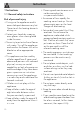
Instructions 1 Instructions 1.1 General safety instructions Risk of personal injury • During use the appliance and its accessible parts become very hot. Never touch the heating elements during use. • Protect your hands by wearing oven gloves when moving food inside the oven. • Never try to put out a fire or flames with water: Turn off the appliance and smother the flames with a fire blanket or other appropriate cover.
• Do not open the storage compartment (where present) when the oven is on and still hot. • The items inside the storage compartment could be very hot after using the oven. • DO NOT USE OR STORE FLAMMABLE MATERIALS IN THE STORAGE COMPARTMENT (IF PRESENT) OR NEAR THE APPLIANCE. • DO NOT USE AEROSOLS IN THE VICINITY OF THIS APPLIANCE WHILST IT IS IN USE. • Switch off the appliance immediately after use. • DO NOT MODIFY THIS APPLIANCE.
Instructions • Never leave the appliance unattended during cooking operations where fats or oils could be released, as these could then heat up and catch fire. Be very careful. • Danger of fire: do not store items on the cooking surfaces. • DO NOT FOR ANY REASON USE THE APPLIANCE AS A SPACE HEATER. • Do not spray any spray products near the oven. • Do not use plastic cookware or containers when cooking food. • Do not put sealed tins or containers in the oven.
• Do not use cleaning products containing chlorine, ammonia or bleach on parts made of steel or that have metallic surface finishes (e.g. anodizing, nickel- or chromium-plating). • Do not use abrasive or corrosive detergents (e.g. scouring powders, stain removers and metallic sponges) on glass parts. • Do not wash removable parts such as the hob pan support grids, flame-spreader crowns and burner caps in the dishwasher. • Never use the oven door to lever the appliance into place when fitting.
Instructions • Ensure that the appliance is switched off before replacing the bulb. • Do not rest any weight or sit on the open door of the appliance. • Take care that no objects are stuck in the doors. 1.2 Manufacturer’s liability The manufacturer declines all liability for damage to persons or property caused by: • Use of the appliance other than that specified • Failure to comply with the instructions in the user manual • Tampering with any part of the appliance • The use of non-original spare parts. 1.
Instructions Plastic packaging Danger of suffocation • Do not leave the packaging or any part of it unattended. • Do not let children play with the plastic bags. 1.7 How to read the user manual This user manual uses the following reading conventions: Instructions General information on this user manual, on safety and final disposal.
Description 2 Description 2.
Description EN 2.2 Hob Zone Dimensions (H x L - mm) min. cookware diameter (mm) Max. power draw (W)* Power draw in Booster function (W)* 1 193 x 193 120 1600 1850. 2 193 x 193 120 2100 2300. 3 210 x 210 120 2200 2300. 4 160 x 160 110 1300 1400. * power levels are indicative and can vary according to the pan used or the settings made.
Description Advantages of induction cooking The hob is equipped with an induction generator for each cooking zone. Each generator located under the glass ceramic cooking surface creates an electromagnetic field which induces a thermal current in the base of the pan. This means the heat is no longer transmitted from the hob to the pan but created directly inside the pan by the inductive current.
Description 4 Programmer clock Cooling fan EN For displaying the current time, setting programmed cooking operations and the minute minder timer. 5 Function knob The oven’s various functions are suitable for different cooking modes. After selecting the required function, set the cooking temperature using the temperature knob. 2.4 Other parts Shelves The appliance features shelves to position trays and racks at different heights. The insertion heights are indicated from the bottom upwards (see 2.
Description Tray rack Deep tray To be placed over the top of the tray; for cooking foods which may drip. Useful for collecting fat from foods placed on the rack above and for cooking pies, pizzas and baked desserts. Tray The oven accessories intended to come into contact with food are made of materials that comply with the provisions of current legislation. Useful for collecting fat from foods placed on the rack above.
Use 3.1 Instructions High temperature inside the oven during use Danger of burns • Keep the oven door closed during cooking. • Protect your hands wearing heat resistant gloves when moving food inside the oven. • Do not touch the heating elements inside the oven. • Do not pour water directly onto very hot trays. • Keep children under the age of 8 away from the oven when it is in use.
Use Improper use Risk of damage to surfaces • Do not cover the bottom of the oven cavity with aluminium or tin foil sheets. • If you wish to use greaseproof paper, place it so that it will not interfere with the hot air circulation inside the oven. • Do not place pans or trays directly on the bottom of the oven cavity. • Do not use the open door to rest pans or trays on the internal glass pane. • Do not pour water directly onto very hot trays.
3.2 Using the accessories Tray rack Racks and trays The tray rack has to be inserted into the tray. In this way fat can be collected separately from the food which is being cooked. Racks and trays have to be inserted into the side guides until they come to a complete stop. • The mechanical safety locks that prevent the rack from being removed accidentally must face downwards and towards the back of the oven cavity. 3.
Use Just turn the knob clockwise to the required power setting. If the symbol appears on the display, it means the pan is not suitable. Cookware suitable for use in induction cooking Cookware used on the induction cooking surface must be made of metal, with magnetic properties and a sufficiently large base. Suitable cookware: • Enamelled steel cookware with thick bases. • Cast iron cookware with an enamelled base.
Use Pans with smaller diameters risk not being detected and therefore not activating the inductor. Limiting the cooking duration The hob has an automatic device which limits the duration of use. If the cooking zone settings are not changed, the maximum duration of operation for each zone depends on the power level selected. When the device for limiting the duration of use is activated, the cooking zone turns off, a short alert sounds and, if the zone is hot, the symbol appears on the display.
Use • Make sure that the pressure cooker contains enough liquid as, if there is not enough and it overheats, this may cause damage to both the pressure cooker and the cooking zone. • If possible, always cover pans with a suitable lid. • Choose a pan suitable for the quantity of food to be cooked. A large, half-empty saucepan leads to a waste of energy.
2. Turn the front left cooking zone knob back to the 0 position and turn the rear left cooking zone knob until it reaches position 9. A prolonged beep will be emitted. The power level can be increased at any moment. The “maximum power” period will automatically be modified. Once the acceleration period is over the power level will remain the same as the one previously selected. If the power is reduced, by turning the knob anti-clockwise, the heating accelerator will automatically be disabled.
Use Power control The hob is fitted with a power control module that optimises/limits consumption. If the overall set power level exceeds the maximum limit permitted, the electronic circuit board will automatically manage the power supplied by the hot plates. The module tries to maintain the maximum deliverable power levels. Levels set by the automatic control will appear on the display.
Activating the hob power limitation function The induction hob is configured to operate at 7.4 kW . However, the maximum power can be limited so that it can work at 4.5 kW or 3 kW. 1. Switch off the cooker’s power supply and wait 10 seconds before turning the power back on. The power level of the hob must be set within 2 minutes of it being connected to the mains power supply. 2.
Use 3.5 Using the oven Switching on the oven To switch on the oven: 1. Select the cooking function using the function knob. 2. Select the temperature using the temperature knob. Functions list Static As the heat comes from above and below at the same time, this system is particularly suitable for certain types of food. Traditional cooking, also known as static cooking, is suitable for cooking just one dish at a time.
Fan with circulaire The combination of the fan and the circulaire heating element (incorporated in the rear of the oven) allows you to cook different foods on several levels, as long as they need the same temperatures and same type of cooking. Hot air circulation ensures instant and even distribution of heat. It will be possible, for instance, to cook fish, vegetables and biscuits simultaneously (on different levels) without odours and flavours mingling.
Use Timed cooking Setting the time If the time is not set, the oven will not switch on. On the first use, or after a power failure, the digits will be flashing on the appliance’s display. 1. Hold down the clock key for two seconds. The dot between the hours and the minutes flashes. 2. The time can be set via the value increase key and value decrease key . Keep the key pressed in to increase or decrease rapidly. 3. Wait 7 seconds. The dot between the hours and the minutes stops flashing. 4.
Use to reset the It is not possible to set a cooking time of more than 10 hours. To cancel the set programming press and hold down the value increase and the value decrease keys at the same time and then turn the oven off manually. 4. Use the or key to set the required minutes. (for example 1 hour) 5. Press the menu key will appear on the display in sequence with the pre-set cooking duration added to the current time (for example, the cooking end time shown is 18:30). 6.
Use 10. Return the function and temperature knobs to 0. 11. To turn off the buzzer just press any key of the programmer clock. 12. Press the and keys at the same time to reset the set program. It is not possible to set a cooking time of more than 10 hours. It is not possible to set a programmed cooking time of more than 24 hours. After setting, hold the menu key down for 2 seconds to display the cooking time remaining. Press the menu key again.
Selecting the buzzer The buzzer can have 3 tones. 1. Hold down the value increase value decrease time. and keys at the same 2. Press the clock key . Press the value decrease key a different buzzer tone. to select 3.7 Cooking advice General advice • Use a fan assisted function to achieve consistent cooking at several levels. • It is not possible to shorten cooking times by increasing the temperature (the food could be overcooked on the outside and undercooked on the inside).
Use Advice for defrosting and proving • Place frozen foods without their packaging in a lidless container on the first shelf of the oven. • Avoid overlapping the food. • To defrost meat, use the rack placed on the second level and a tray on the first level. In this way, the liquid from the defrosting food drains away from the food. • Bread and fruit, if divided into pieces, will take the same amount of time to defrost, regardless of the total weight and quantity.
Use Cooking information table Function Shelf Temperature (°C) Time (minutes) Lasagne Pasta bake 3-4 3-4 Static Static 1 1 220 - 230 220 - 230 45 - 50 45 - 50 Veal roast Pork loin Sausages Roast beef Roast rabbit Turkey breast Roast pork neck Roast chicken 2 2 1.5 1 1.5 3 2-3 1.
Cleaning and maintenance 4 Cleaning and maintenance 4.2 Cleaning the surfaces 4.1 Instructions To keep the surfaces in good condition, they should be cleaned regularly after use. Let them cool first. Improper use Risk of damage to surfaces • Do not use steam jets to clean the appliance. • Do not use cleaning products containing chlorine, ammonia or bleach on parts made of steel or that have metallic surface finishes (e.g. anodizing, nickelor chromium-plating).
4.3 Cleaning the hob Weekly cleaning Cleaning the glass ceramic hob Clean and maintain the hob once a week using an ordinary glass ceramic cleaning product. Always follow the manufacturer’s instructions. The silicon in these products creates a protective, water-repellent membrane which also resists dirt. All marks stay on the membrane and can therefore be removed easily. After cleaning, dry the surface with a clean cloth.
Cleaning and maintenance 4.4 Cleaning the door Removing the door For easier cleaning it is recommended to remove the door and place it on a tea towel. To remove the door proceed as follows: 1. Open the door completely and insert two pins into the holes on the hinges indicated in the figure. 3. To reassemble the door, put the hinges in the relevant slots in the oven, making sure that grooved sections A are resting completely in the slots.
Removing the internal glass panes For easier cleaning the internal glass panes of the door can be removed. 1. Remove the internal glass pane by pulling the rear part gently upwards, following the movement indicated by the arrows (1). This way, the 4 pins attached to the glass detach from their housings in the oven door. 2. Then, pull the front part upwards (2). 3.
Cleaning and maintenance 4.5 Cleaning the oven cavity Cleaning the racks and trays In order to keep your oven in the best possible condition, clean it regularly after letting it cool down. Avoid letting food residue dry inside the oven cavity, as this could damage the enamel. Take out all removable parts. Clean the racks and trays with warm water and non-abrasive detergents. Carefully rinse and dry damp parts.
Vapor Clean Vapor Clean is an assisted cleaning procedure which facilitates the removal of dirt. Thanks to this process, it is possible to clean the inside of the oven very easily. The dirt residues are softened by the heat and water vapour for easier removal afterwards. • Spray a water and washing up liquid solution inside the oven using a spray nozzle. Direct the spray towards the side walls, upwards, downwards and towards the deflector.
Cleaning and maintenance End of the Vapor Clean cycle 4.6 Extraordinary maintenance 4. Open the door and wipe away the less stubborn dirt with a microfibre cloth. 5. Use a non-scratch sponge with brass filaments on hard to remove deposits. 6. In case of grease residues use specific oven cleaning products. 7. Remove the water left inside the oven.
Cleaning and maintenance Replacing the internal light bulb 4. Slide out and remove the light bulb. EN Live parts Danger of electrocution • Unplug the appliance. • Use protective gloves. 1. Completely remove all accessories from inside the oven. 2. Remove the rack/tray support frames. 3. Remove the bulb cover using a tool (e.g. a screwdriver). Pay attention not to scratch the oven cavity enamel. Do not touch the halogen light bulb directly with your fingers, but wrap it in insulating material. 5.
Installation 5 Installation 5.1 Positioning Heavy appliance Crushing hazard • Position the appliance into the cabinet cut-out with the help of a second person. Pressure on the open door Risk of damage to the appliance Any wall units installed above the appliance’s worktop must be positioned at least Y mm from it. If a hood is installed above the hob, refer to the hood instruction manual to ensure the correct clearance is left.
Installation EN Appliance overall dimensions B - Class 2 subclass 1 (Built-in appliance) A 600 mm B 600 mm C1 D min. 150 mm 900 - 915 mm H 750 mm I 450 mm L2 600 mm 1 Minimum distance from side walls or other flammable material. 2 Minimum cabinet width (=A). C - Class 2 subclass 1 (Built-in appliance) The appliance must be installed by a qualified technician and according to the regulations in force.
Installation Appliance dimensions: location of electrical connection (mm) Positioning and levelling Heavy appliance Risk of damage to the appliance • Insert the front legs first and then the rear ones. After making the electrical and/or gas connections, screw the four adjustable legs supplied with the appliance. A 124 B 32 F min. 70 - max. 110 H 803 L 598 E = Electrical connection 90 The appliance must sit level on the floor to ensure stability.
Installation Fastening to the wall 3. Assemble the fastening bracket. EN The anti-tip devices must be installed in order to prevent the appliance from tipping over. 1. Screw the wall fastening plate to the rear of the appliance. 2. Adjust the height of the 4 legs. 4. Align the base of the hook on the fastening bracket with the base of the slot on the wall fastening plate.
Installation 5. Align the base of the fastening bracket with the ground and tighten the screws to fix the measurements. 6. Use 50 mm for the distance from the side of the appliance to the bracket holes. 92 7. Move the bracket onto the wall and mark the position of the holes to be drilled in the wall. 8. After drilling the holes in the wall, use wall plugs and screws to fasten the bracket to the wall. 9.
Installation 5.2 Electrical connection • 220-240 V 3~ • Have the electrical connection performed by authorised technical personnel. • Use personal protective equipment. • The appliance must be connected to earth in compliance with electrical system safety standards. • Disconnect the mains power supply. • Do not pull the cable to remove the plug. • Use cables withstanding a temperature of at least 90°C. • The tightening torque of the screws of the terminal supply wires must be 1.5 - 2 Nm.
Installation Access to the terminal board To connect the power supply cable, you must access the terminal board on the rear casing: 1. Remove the screws fastening the plate to the rear casing. 3. Proceed with installation of the power supply cable. It is recommended to slacken off the cable clamp screw before installing the power supply cable. 2. Gently rotate the plate and remove it from its seat. 94 4.
Installation Fixed connection EN Fit the power line with an all-pole disconnection switch, with a clearance between its contacts that allows the complete disconnection as per the overvoltage category III, in compliance with the installation regulations. Replacement clamp In the event of a single-phase or two-phase supply with a three-core 3 x 10 mm² cable, the existing clamp must be replaced with the one supplied in order to ensure that the cable is correctly fastened. 5.