Contents 1.1 1.2 1.3 1.4 1.5 1.6 1.7 How to read the user manual This user manual Appliance purpose General safety instructions Manufacturer liability Identification plate Disposal 2 Description 2.1 2.2 2.3 2.4 2.5 General Description Cooking hob Control panel Other parts Available accessories 3 Use 3.1 3.2 3.3 3.4 3.5 3.6 3.7 3.8 Instructions Cleaning the appliance Removing the door Cleaning the door glazing Cleaning the inside of the oven Extraordinary maintenance 5 Installation 5.1 5.2 5.3 5.
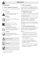
Instructions 1 Instructions 1.1 How to read the user manual This user manual uses the following reading conventions: Instructions General information on this user manual, on safety and final disposal. Description Description of the appliance and its accessories. Use Information on the use of the appliance and its accessories, cooking advice. Cleaning and maintenance Information for proper cleaning and maintenance of the appliance.
For this appliance • Do not obstruct ventilation openings and heat dispersal slots. • Do not insert pointed metal objects (cutlery or utensils) into the slots in the appliance. • Do not rest any weight or sit on the open door of the appliance. • Take care that no objects are stuck in the doors. • Do not use the appliance to heat rooms for any reason. 1.
Description 2 Description 2.1 General Description 1 Skirt 2 Cooking hob 3 Control panel 4 Oven light 5 Seal 6 Door 7 Fan 8 Storage compartment 2.
Description EN 2.3 Control panel Hob burner knobs (1) Clock (4) Useful for lighting and adjusting the hob burners and the coup de feu hot plate (where present). Press and turn the knobs anti-clockwise to the value to light the relative burners. Turn the knobs to the zone between the maximum and minimum setting to adjust the flame. Return the knobs to the position to turn off the burners. Useful for displaying the current time and programming the minute minder timer.
Description 2.4 Other parts 2.5 Available accessories Shelves The appliance features shelves for positioning trays and racks at different heights. The insertion heights are indicated from the bottom upwards (see 2.1 General Description). Some models are not provided with all accessories. Rack Cooling fan The fan cools the oven and comes into operation during cooking.
Description WOK Reduction pan stand EN Oven tray Useful when using a wok. Useful for collecting fat from foods placed on the rack above. Rotisserie The accessories intended to come into contact with food are made of materials that comply with the provisions of current legislation. Original and optional accessories can be requested to Authorised Assistance Centres. Use only original accessories supplied by the manufacturer.
Use 3 Use 3.1 Instructions High appliance temperature during use Danger of burns • Keep the oven door closed during cooking. • Protect your hands using heat resistant gloves when moving food inside the oven. • Do not touch the heating elements inside the oven. • Do not pour water directly onto very hot trays. • Do not allow children younger than 8 years old to come near the appliance when in operation.
Use • Do not cover the bottom of the cooking compartment with aluminium or tin foil sheets. • If you wish to use greaseproof paper, place it so that it will not interfere with the hot air circulation inside the oven. • Do not place pans or trays directly on the bottom of the cooking compartment. • Do not use the open door to rest pans or trays on the internal glass panel. • The cooking vessels or griddle plates should be placed inside the perimeter of the hob. • All pans must have smooth, flat bottoms.
Use Tray rack Rotisserie The tray rack can be inserted into the tray. In this way fat can be collected separately from the food which is being cooked. • Place the rotisserie supports into the inserts at the corners of the tray. The supports should be placed as shown in the figure below. • Prepare the rotisserie rod with the food using the clip forks provided. The clip forks can be tightened using the fastening screws. Reduction pan stands The reduction pan stands have to be placed on the hob grids.
Use Pour a little water into the drip tray to prevent smoke from forming. 3.4 Using the hob • Place the tray on the first runner (see “General Description”). Rocking the rotisserie supports, insert the tip of the rotisserie rod into the hole of the rotisserie motor on the side of the oven. All the appliance's control and monitoring devices are located together on the front panel. The burner controlled by each knob is shown next to the knob. The appliance is equipped with an electronic ignition device.
Use Correct position for flame-spreader crowns and burner caps Before lighting the hob burners, make sure that the flame-spreader crowns are correctly positioned in their housings with their respective burner caps. Make sure that the holes 1 in the flame-spreader crowns are aligned with the igniters 3 and thermocouples 2. 3.5 Using the storage compartment The storage compartment is at the bottom of the cooker. To open it, pull the handle towards you.
Functions list Static As the heat comes from above and below at the same time, this system is particularly suitable for certain types of food. Traditional cooking, also known as static cooking, is suitable for cooking just one dish at a time. Perfect for all types of roasts, bread and cakes and in any case particularly suitable for fatty meats such as goose and duck. Fan-assisted static The operation of the fan, combined with traditional cooking, ensures uniform cooking even with complex recipes.
Use Fan-assisted circular The combination of the fan and the circular element (incorporated in the rear of the oven) allows you to cook different foods on several levels, as long as they need the same temperatures and same type of cooking. Hot air circulation ensures instant and uniform distribution of heat. It will be possible, for instance, to cook fish, vegetables and biscuits simultaneously (on different levels) without mixing odours and flavours.
Use Advice for cooking desserts and biscuits • Use dark metal moulds: they help to absorb the heat better. • The temperature and the cooking time depend on the quality and consistency of the dough. • To check whether the dessert is cooked right through: at the end of the cooking time, put a toothpick into the highest point of the dessert. If the dough does not stick to the toothpick, the dessert is cooked.
Use 3.8 Analogue programmer Programmed cooking Programmed cooking is the function which allows a cooking operation to be started at a set time and then ended after a specific length of time set by the user. A Setting knob B Cooking window C Cooking start pointer Setting the time To set the time, push in setting knob A and turn it clockwise. 1. Turn setting knob A until the 0 symbol appears in the cooking window B. 2.
Use Timed cooking is the function which allows a cooking operation to be started and then ended after a specific length of time set by the user. 1. Turn setting knob A until the 0 symbol appears in the cooking window B. 2. Pull out setting knob A, turn it clockwise to position the cooking start pointer C to the current time. 3. Turn setting knob A clockwise until the required cooking time (0... 180 minutes) is selected in the cooking window B. 4.
Use Cooking information table Food Weight (Kg) Function Lasagne Oven-baked pasta 3-4 2 Static Static Roast veal Pork loin Pork shoulder Roast rabbit Turkey breast Roast pork neck Roast chicken 1.2 1.2 1.2 1.2 1.5 2 1.
Cleaning and maintenance 4.1 Instructions Improper use Risk of damage to surfaces • Do not use steam jets for cleaning the appliance. • Do not use cleaning products containing chlorine, ammonia or bleach on steel parts or parts with metallic finishes on the surface (e.g. anodizing, nickel- or chromium-plating). • Do not use abrasive or corrosive detergents on glass parts (e.g. powder products, stain removers and metallic sponges). • Do not use rough or abrasive materials or sharp metal scrapers.
Cleaning and maintenance Igniters and thermocouples For correct operation the igniters and thermocouples must always be perfectly clean. Check them frequently and clean them with a damp cloth if necessary. Remove any dry residues with a wooden toothpick or a needle. 4.3 Removing the door For easier cleaning, the door can be removed and placed on a canvas. To remove the door proceed as follows: 1. Open the door completely and insert two pins into the holes on the hinges indicated in the figure. 56 2.
Cleaning and maintenance The glass in the door should always be kept thoroughly clean. Use absorbent kitchen roll. In case of stubborn dirt, wash with a damp sponge and an ordinary detergent. We recommend the use of cleaning products distributed by the manufacturer. 4.5 Cleaning the inside of the oven For the best oven upkeep, clean it regularly after having allowed it to cool. • Take out all removable parts. • Clean the oven racks with warm water and non-abrasive detergent.
Cleaning and maintenance 4.6 Extraordinary maintenance Live parts Danger of electrocution • Disconnect the oven power supply. Removing the seal of the auxiliary oven To permit thorough cleaning of the oven, the door seal can be removed. There are hooks on all four sides to attach it to the edge of the oven. Pull the edges of the seal outwards to detach the hooks. Replacing the internal light bulb 1. Unscrew bulb protector 1, anticlockwise. 2. Replace the bulb 2 with one of the same type (25W).
Installation 5.1 Gas connection Gas leak Danger of explosion • After carrying out any operation, check that the tightening torque of gas connections is between 10 Nm and 15 Nm. • If required, use a pressure regulator that complies with current regulations. • At the end of the installation, check for any leaks with a soapy solution, never with a flame.
Installation it with clamp 5 (which must be compliant with the applicable standard). Connection with a flexible steel hose Make the connection to the gas mains using a continuous wall flexible steel hose whose specifications comply with the current regulations. Carefully screw the connector 3 to the gas connector 1 of the appliance, placing the seal 2 between them. Connection using a rubber hose complying with current standards is only permitted if the hose can be inspected along its entire length.
Installation Make the connection to the gas mains using a continuous wall flexible steel hose whose specifications comply with the current regulations. Carefully screw the hose connector 3 to the appliance’s gas connector 1 (½” thread ISO 228-1), placing the supplied seal 2 between them. Apply insulating material to the thread of connector 3, then tighten the flexible steel hose 4 to the connector 3.
Installation When the job is complete, the installer must issue a certificate of conformity. 5.2 Adaptation to different types of gas The appliance is pre-set for natural gas G20 (2H) at a pressure of 20 mbar. In case of operation with other types of gas, the burner nozzles must be changed and the minimum flame adjusted on the gas taps. Replacing nozzles 1 Extraction using a hood 2 Extraction without a hood 1. Remove the pan stands, burner caps and flame-spreader crowns to access the burner casings. 2.
Installation Light the burner and turn it to the minimum position. Extract the gas tap knob and turn the adjustment screw next to the tap rod (depending on the model) until the correct minimum flame is achieved. Refit the knob and verify that the burner flame is stable. Turn the knob rapidly from the maximum to the minimum setting: the flame should not go out. Repeat the operation on all gas taps.
Installation Gas types and Countries Gas types 1 Natural Gas G20 G20 20 mbar G20/25 20/25 mbar 2 Natural Gas G25 G25 25 mbar 3 Natural Gas G25 G25 20 mbar 4 LPG G30/31 G30/31 28/37 mbar G30/31 30/37 mbar G30/31 30/30 mbar 5 LPG G30/31 G30/31 50 mbar 6 City Gas G110 G110 8 mbar 7 City Gas G120 G120 8 mbar 64 IT • GB-IE FR-BE • DE AT • • NL ES PT SE RU DK • • • • • • • • • • • • • • • • • • • • • • •
Installation 1 Natural Gas G20 Rated heating capacity (kW) Nozzle diameter (1/100 mm) Pre-chamber (printed on nozzle) Reduced capacity (W) 2 Natural Gas G25 Rated heating capacity (kW) Nozzle diameter (1/100 mm) Pre-chamber (printed on nozzle) Reduced capacity (W) 3 Natural Gas G25 Rated heating capacity (kW) Nozzle diameter (1/100 mm) Pre-chamber (printed on nozzle) Reduced capacity (W) 4 LPG G30/31 Rated heating capacity (kW) Nozzle diameter (1/100 mm) Reduced capacity (W) Rated capacity G30 (g/h) Rated c
Installation 5.3 Electrical connection Power voltage Danger of electrocution • Have the electrical connection performed by authorised technical personnel. • Use personal protective equipment. • The appliance must be connected to earth in compliance with electrical system safety standards. • Disconnect the main power supply. • Do not pull the cable to remove the plug. • Use H05V2V2-F cables withstanding a temperature of at least 90°C.
Installation Fixed connection Connection with plug and socket Make sure that the plug and socket are of the same type. Avoid using adapters and shunts as these could cause overheating and a risk of burns. 5.4 Positioning Heavy appliance Danger of crush injuries Heat production during appliance operation Risk of fire • Veneers, adhesives or plastic coatings on adjacent furniture should be temperature-resistant (no less than 90°C).
Installation Depending on the type of installation, this appliance belongs to classes: C - Class 2 subclass 1 A - Class 1 (Free-standing appliance) (Built-in appliance) The appliance must be installed by a qualified technician and according to the regulations in force. Fastening to wall (where present) Heavy appliance Risk of damages to the appliance • Insert the front feet first and then the rear ones.
Installation EN 1. Use the adjustable feet to level the appliance until it is level and stable on the ground. 2. Fasten a hook bolt (not supplied) into the wall at a height (H) of 800 mm from the floor. Assembling the skirt The skirt provided is an integral part of the product; it must be fastened to the appliance prior to installation. The skirt must always be positioned and secured correctly on the appliance. 1. Place the skirt on the worktop. 2.
Installation Installing the handrails The handrails provided are an integral part of the product; they must be fastened to the appliance prior to installation. Position the handrail on the supports. Try to insert the two supports parallel in each handrail's openings. There are 6 threaded holes along the hob for fitting the handrail. Use a 2 mm Allen key to screw the hex socket screws into the fastening holes to fasten the handrails to the supports.