Index 1. INSTRUCTIONS FOR SAFE AND PROPER USE________________ 4 2. POSITIONING OF HOB ____________________________________ 6 3. GAS CONNECTION ______________________________________ 11 4. ELECTRICAL CONNECTION ______________________________ 12 5. GAS CONNECTION ______________________________________ 13 6. ADAPTATION TO DIFFERENT TYPES OF GAS _______________ 15 7. FINAL OPERATIONS _____________________________________ 17 8. USING THE HOB ________________________________________ 19 9.
Introduction 1. INSTRUCTIONS FOR SAFE AND PROPER USE THIS MANUAL IS AN INTEGRAL PART OF THE APPLIANCE AND THEREFORE MUST BE KEPT IN ITS ENTIRETY AND IN AN ACCESSIBLE PLACE FOR THE WHOLE WORKING LIFE OF THE COOKING HOB. WE ADVISE READING THIS MANUAL AND ALL THE INSTRUCTIONS THEREIN BEFORE USING THE COOKING HOB. ALSO KEEP THE SERIES OF NOZZLES SUPPLIED. INSTALLATION MUST BE CARRIED OUT BY AUTHORISED PERSONS IN ACCORDANCE WITH THE REGULATIONS IN FORCE.
Introduction THE IDENTIFICATION PLATE, WITH TECHNICAL DATA, SERIAL NUMBER AND MARKING IS CLEARLY VISIBLE UNDER THE CASING. THE PLATE ON THE CASING MUST NOT BE REMOVED. BEFORE CONNECTING THE DEVICE, MAKE SURE THAT IT HAS BEEN REGULATED FOR THE TYPE OF GAS THAT WILL FEED IT, CHECKING THE LABEL UNDER THE CASING. DO NOT PUT PANS WITHOUT PERFECTLY SMOOTH AND FLAT BOTTOMS ON THE COOKING HOB GRIDS. DO NOT USE RECIPIENTS OR GRIDDLE PLATES THAT EXTEND BEYOND THE EXTERNAL PERIMETER OF THE HOB.
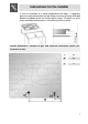
Instructions for the installer 2. POSITIONING OF HOB It is the law that all gas appliances are installed by authorised persons. Clearance around the appliance must comply with the requirements of AS5601. The following operation requires building and/or carpentry work so must be carried out by a competent tradesman. Installation can be carried out on various materials such as masonry, metal, solid wood or plastic laminated wood as long as they are heat resistant (T 90°C). 2.1.
Instructions for the installer In case of installation on a hollow compartment with doors, a separating panel has to be placed under the hob. Keep a minimum distance of 10 mm between the bottom of the unit and the panel surface. The panel has to be easily removable to allow access in the event of technical service. Overall dimensions: location of gas and electrical connection points (all measures in mm).
Instructions for the installer 2.2 Clearance above and around domestic appliances Extract from AS5601 REQUIREMENTS 1 Overhead clearances – (Measurement A) Range hoods and exhaust fans shall be installed in accordance with the manufacturer’s instructions. However, in no case shall the clearance between the highest part of the hob of the cooking appliance and a range hood be less than 600 mm or, for an overhead exhaust fan, 750 mm.
Instructions for the installer Where B, measured from the periphery of the nearest burner to any vertical combustible surface, is less than 200 mm, the surface shall be protected in accordance with Clause 5.12.1.2 to a height C of not less than 150 mm above the hob for the full dimension (width or depth) of the cooking surface area. Where the cooking appliance is fitted with a ‘splashback’, protection of the rear wall is not required.
Instructions for the installer 2.3 Room ventilation Caution – This hob may only be installed and operated in rooms permanently ventilated in accordance with current regulations. For proper operation of a gas appliance it is essential for the air necessary for combustion of the gas to be able to flow naturally into the room. Air must flow directly into the room through openings in its outside walls.
Instructions for the installer 3. GAS CONNECTION This appliance is suitable for installation with Natural Gas or LPG (propane). Refer to page 12 for the relevant burner pressure and appropriate injector sizes. When the appliance is to be connected to Natural Gas then the pressure regulator supplied must be fitted to the gas inlet. A test point (for checking the gas pressure) is supplied either with the regulator or as a separate fitting in the case of LPG (propane) appliances.
Instructions for the installer 4. ELECTRICAL CONNECTION Make sure that the voltage and capacity of the power line conform to the data shown on the plate located under the casing. Do not remove this plate for any reason. The plug on the end of the supply cable and the wall socket must be the same type and conform to the current electrical system regulations. Check that the power line is adequately grounded.
Instructions for the installer 5. GAS CONNECTION Connection to the gas mains may be made with a rigid copper pipe or with a flexible pipe and conforming to the provisions defined by standard regulations in force. To facilitate connection, fitting A on the rear of the appliance may be adjusted laterally. For this purpose, loosen hexagon nut B, turn fitting A to the desired position, and retighten hexagon nut B (tightness is ensured by a biconical brass ring).
Instructions for the installer 5.1 Connection to LPG Use a pressure regulator and make the connection to the tank according to the provisions of standards regulations in force. Make sure that feed pressure conforms to the levels shown in the table in paragraph “6.2 Regulation for LPG”. 5.2 Ventilation of rooms The hob may be installed only in rooms with permanent ventilation, as required by standards regulations in force.
Instructions for the installer 6. ADAPTATION TO DIFFERENT TYPES OF GAS Before performing any cleaning or maintenance work, detach the appliance from the electrical socket. The hob has been inspected for NG natural gas at a pressure of 1.0 kPa. For functioning with other types of gas the nozzles must be replaced and the primary air adjusted. To replace the nozzles and regulate the burners, you have to remove the top as described in the following paragraph. 6.1 Removing the hob 1. 2. 3. 4. 5. 6.
Instructions for the installer 6.2 Regulation for LPG Loosen screw A and push support B all the way. Use a double head wrench to remove nozzle C and assemble the suitable one, following the instructions indicated in the reference charts, with respect to the type of gas to use. The screwing torque of the nozzle should never exceed 3 Nm. Reposition support B so that nozzle C is covered perfectly. Place the burner on its support and ignite it.
Instructions for the installer 6.3 Regulation for natural gas The hob has been adjusted for natural gas at a pressure of 1.0kPa. To allow the unit to work back with this type of gas, after it has been adjusted for LPG, perform the same operations described in paragraph “6.2 Regulation for LPG”, but refer to the following table for the proper injectors. NG – 1.0 kPa Burner Auxiliary (1) Semi rapid (2) Rapid (3) Rapid (4) Wok (5) Nominal gas consumption (MJ/h) 4.8 6.0 11.5 12.2 15.0 Injector (mm) 0.98 1.
Instructions for the installer 7.3 Arrangement of burners on hob BURNERS 1 2 3 4 5 Auxiliary Semi-rapid Rapid Rapid WOK 7.4 Lubrification of gas taps After a while, the gas tap may become hard to turn or lock. If this happens, it has to be cleaned inside and re-greased. This must be done by a qualified technician.
Instructions for the user 8. USING THE HOB Before turning on the burners, make sure that the burner rings, caps and grids have been fitted correctly. In the ultrarapid burner, notch A must be aligned with pin B. Grid C provided is intended for use with woks (Chinese pans). Adapter D comes only with open grids models and is intended for use with small sized vessels. Some models do not feature all accessories. 8.1 Ignition of the burners For each knob the corresponding burner is indicated.
Instructions for the user 8.2 Practical advice for using the burners For better burner performance and minimum gas consumption, flat bottomed, even recipients must be used, with covers and proportional in size to the burners (see paragraph “8.3 Diameter of containers”). To avoid overcooking or damage to the surface top while cooking, all recipients or griddles must be positioned within the cooking hob perimeter and must be a minimum distance of 3-4 cm from the knobs. 8.
Instructions for the user 8.4.2 Using the electric elements The electric elements are ideal for ultrarapid cooking. The settings shown in the table are merely indicative. POSITION HEAT INTENSITY POSSIBLE COOKING 0 Off - 1 Weak To melt butter, chocolate, etc. To heat small amounts of liquid. 2 Soft To heat larger amounts of liquid. 3 Slow To defrost frozen food and prepare stews, cooking at or just below boiling point.
Instructions for the user 9. CLEANING AND MAINTENANCE Before any intervention, disconnect the power supply of the device. 9.1 Cleaning Clean the cooking top regularly every time you use it, obviously after it has cooled. NEVER USE A STEAM JET TO CLEAN THE APPLIANCE. 9.1.1 Regular daily cleaning of the hob In order to clean and preserve the surface, always use specific products only, which do not contain abrasive substances or chlorine-based acid substances.
Instructions for the user 9.2.1 Ignition plugs and safety devices For good functioning of the lighting ignition plugs and the safety devices, keep them very clean. Check frequently and clean with a damp cloth when necessary. 9.2.2 The cover Clean the glass or steel cover, where mounted, with warm water. Never use abrasive sponges or detergents. To clean the rear part of the cooktop, remove the cover by lifting out. When finished cleaning, refit the cover making sure to insert it correctly.
Instructions for the user 10.PROBLEMS AND CAUSES Each of the following cases is caused by an abnormal operation of the appliance and should be dealt with by a authorised persons: please contact your local dealer or Service Center in case you detect any of these malfunctioning. PROBLEM CAUSE WHAT TO DO The flame is very long with bright yellow tips. Black deposits on the bottom of the pans. Defect of comburent air or incorrect injectors. Burner dirty or flame ports obstructed. Clean the burner.