Table of Contents - Important Safety Instructions 1. IMPORTANT SAFETY INSTRUCTIONS ................................................................................. 4 2. DIMENSION REQUIREMENTS ............................................................................................... 7 3. UNPACKING, MOVING AND POSITIONING THE RANGE .................................................... 9 4. WALL ATTACHMENT AND THE ANTI-TIP DEVICE ............................................................ 10 5.
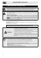
Important Safety Instructions 1. IMPORTANT SAFETY INSTRUCTIONS READ AND SAVE THESE INSTRUCTIONS – Your safety and the safety of others are very important. We have provided many important safety messages throughout this manual and on the appliance. Read all the instructions before using the appliance and always obey all safety messages. RECOGNIZE SAFETY INFORMATION This is a safety alert symbol. This symbol alerts you to potential hazards that can result in severe personal injury or loss of life.
Important Safety Instructions TIP OVER HAZARD WARNING - A child or adult can tip the range and be killed. - Make sure that the anti-tip device has been properly installed and engaged. The wall-mounted brackets should anchor the sides of the range (primary system) or, in case of floor-mounted brackets, they should anchor the rear of the range to the ground. - Make sure that the anti-tip device is re-engaged when the range is moved.
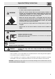
Important Safety Instructions - ELECTRICAL GROUNDING REQUIRED: See the “Electrical Requirements” section. It is the customer’s responsibility: 1 To contact a qualified electrician to install the appliance 2 To ensure that the electrical system is adequate and conforms with the national ANSI / NFPA 70 ELECTRICAL CODE – latest edition – Or the CANADIAN ELECTRICAL CODE, C22.11 – 1 and C22.2 No. 01982 – or latest edition – and all local codes and ordinances.
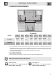
Instructions for the installer 2. DIMENSION REQUIREMENTS CLEARANCE MODEL A B C(5) G(3) I(4) L(1) M(2) N C24GGXU 612 mm 24 ” 636 mm 25 “ 216 mm 8 1/2 ” 612 mm 24 “ 457 mm 18 “ 610 mm 24 “ 330 mm 13 “ 150 mm 5 15/16 ” C36GGXU 912 mm 35 15/16 ” 636 mm 25 ” 216 mm 8 1/2 ” 912 mm 35 15/16 ” 457 mm 18 ” 610 mm 24 ” 330 mm 13 ” 150 mm 5 15/16” 1 min. when bottom of wood or metal cabinet is protected by not less than ¼” (0.64 cm) flame retardant millboard covered with not less than No.
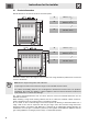
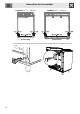
Instructions for the installer 2.1 Product dimensions Overall dimensions: location of electrical connection points. A B C D A B C D 60 mm - 2 3/8 ” 698 mm - 27 7/16 “ 753 mm - 29 5/8 “ 155 mm - 6 1/8 ” 157 mm - 6 3/16 ” 212 mm - 8 3/8 ” 55 mm - 2 1/8 ” 698 mm - 27 7/16 “ 753 mm - 29 5/8 “ 155 mm - 6 1/8 ” 157 mm - 6 3/16 ” 212 mm - 8 3/8 ” Check the location where the range is to be installed. The range should be positioned for convenient access in the kitchen.
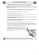
Instructions for the installer 3. UNPACKING, MOVING AND POSITIONING THE RANGE CAUTION: This unit is designed as a cooking appliance. For safety purposes, never use it for warming the room or as a space heater. - It is recommended that the grates, the griddle plate and burner heads, burner caps, front kick panel and oven racks be removed to facilitate handling. This will reduce the weight for moving. - Remove the outer carton and packing material from the shipping base.
Instructions for the installer 4. WALL ATTACHMENT AND THE ANTI-TIP DEVICE TIP OVER HAZARD WARNING - A child or adult can tip the range and be killed. - Make sure that the anti-tip device has been properly installed and engaged. The wall-mounted brackets should anchor the sides of the range (primary system) or, in case of floor-mounted brackets, they should anchor the rear of the range to the ground. - Make sure that the anti-tip device is re-engaged when the range is moved.
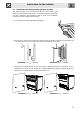
Instructions for the installer 4.1 Instructions for wall mounting (primary system) The anti-tip brackets are to be attached to the rear wall as shown. The height of bracket location from the floor is determined after the range legs have been adjusted to the installation height as shown in the installation instructions and the range has been leveled. 1 Level the range using the adjustable leveling legs. 2 From the floor, measure the height of the notch found on the bracket.
Instructions for the installer C24GGXU (23 15/16 ” - 608 mm) C36GGXU (35 3/4 ” - 908 mm) (Front view) (Front view) 4 Correctly position the range so that the two screws perfectly align with the anti-tip brackets on the range.
Instructions for the installer 5. ELECTRICAL REQUIREMENTS WARNING ELECTRICAL GROUNDING INSTRUCTIONS ELECTRICAL SHOCK HAZARD - Plug into a grounded 3-prong outlet. - Do not cut or remove the grounding prong. - Do not use an adaptor. - Do not use an extension cord. - Check with a qualified electrician if you are not sure whether the range is grounded. WARNING FAILURE TO FOLLOW THESE INSTRUCTIONS COULD RESULT IN LOSS OF LIFE, FIRE OR ELECTRICAL SHOCK.
Instructions for the installer 6. GAS SUPPLY REQUIREMENTS EXPLOSION HAZARD WARNING - Use a new AGA or CSA-approved gas supply line. - Install a shut-off valve. - Securely tighten all gas connections. - lf connected to LP, have a qualified technician ensure that the gas pressure does not exceed a 14" W.C.P. - Examples of qualified technicians include licensed heating personnel, authorized gas company personnel, and authorized service personnel.
Instructions for the installer Always use pipe-joint compound made for use with NATURAL GAS and L.P. GAS between pressure regulator D and NPT adaptor C and between pressure regulator D and pipe E. If a flexible metal conductor is used, make sure that the tubing is not kinked. 3) Use only pipes (E) conforming to standard regulations in force, inserting gasket B (supplied) between fitting A adaptor C.
Instructions for the installer 16 5) Incoming line pressure upstream from the regulator must be 1” (2.5 cm) W.C.P. higher than the manifold pressure in order to check the regulator. Incoming line pressure to the regulator should be as follows for operation and checking the regulator setting: - NATURAL GAS: manifold pressure 4” W.C.P. Incoming line pressure 3.5”-10.5” W.C.P. - LP GAS: manifold pressure 11” W.C.P. Incoming line pressure 8.0”-13” W.C.P. 6) Line pressure testing: Testing above 112 PSI (3.
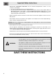
Important Safety Instructions IMPORTANT SAFETY INSTRUCTIONS WARNING: If the instructions contained in this manual are not followed precisely, fire or explosion may result causing property damage, personal injury or loss of life. - Do not store or use gasoline or other flammable vapors or liquids near this or any other appliance. WHAT TO DO IF YOU SMELL GAS • Do not try to light any appliance. • Do not touch any electrical switches. • Do not use any telephones in your building.
Important Safety Instructions The safety messages will inform you of potential hazards, on how to avoid the risk of injury and what can occur if the instructions are not followed. IMPORTANT: Observe all governing codes and ordinances. WARNING: For your safety, the instructions contained in this manual must be followed to minimize the risk of fire or explosion and to prevent property damage, personal injury or loss of life.
Conversion Kit Check that the main gas supply line to the range is shut off and that the power supply cord is disconnected. 1) 2) Remove access cap “A” by using a screwdriver or a coin, turning the access cap counterclockwise. The gas pressure regulator has two settings which are indicated on two sides of the cap. Turn the cap and reinstall it in the regulator with "LP" visible from the outside of the regulator. Incoming line pressure upstream from the regulator must be 1” (2.5 cm) W.C.P.
Conversion Kit Replacing the oven's burners nozzles (This operation does not require primary air regulation). C24GGXU (23 15/16 ” - 608 mm) 1) Oven burner: Open the oven door and remove any accessories that are inside. 2) Lift up the oven surface and pull it outwards. 3) Loosen the screws A and B. 4) 4) Move away the lock that secures the thermocouple and igniter to the burner with screw A. 5) Slide the burner outwards until the nozzle is accessible. 6) Replace the nozzle using a 7mm socket wrench.
Conversion Kit Replacing the oven's burners nozzles (This operation does not require primary air regulation). C36GGXU (35 3/4 ” - 908 mm) 1) Oven burner: Open the oven door and remove any accessories that are inside. 2) Unscrew the two fastening screws before removing the oven floor. 3) Lift the oven floor and slide it out. 5) 4) Unscrew the burner's fastening screw. 5) Remove the burner from its place by sliding it out and moving it to the side.
Conversion Kit 6) Using a 7mm socket wrench replace the nozzle, installing the one that is appropriate for the type of gas to be used. Refer to the gas charts at point 5. 7) WARNING: The tightening torque of the nozzle must be equal to 4 Nm. After replacing the nozzle, put the burner back in its place. (Make sure not to damage the thermocouple or the spark electrode during this operation). 8) Screw in the burner's fastening screw. 9) Reposition the oven floor making sure to insert it correctly.
Conversion Kit 1) Broil burner: Open the oven door and remove any accessories that are inside. 2) Unscrew the two fastening screws for the burner. 3) Remove the burner by sliding it from its place and reposition it as shown in the picture. (Make sure not to damage the thermocouples and the spark electrode). 4) Using a 13mm socket wrench replace the nozzle, installing the one that is appropriate for the type of gas to be used. Refer to the gas charts at point 5.
Conversion Kit 6) To adjust the range for LP gas or to return to Natural Gas use, refer to the charts below. C24GGXU (23 15/16 ” - 608 mm) Natural gas Qt Injector Qr BTU Ø mm BTU Front Right 6200 1.20 1500 Front Left 6200 1.20 1500 Rear Left 3400 0.90 1200 0.80 1000 1.65 2000 Rear Right Inner Outer 14400 Oven 11500 1.60 3000 Broiler 11000 1.55 - Qt Injector Qr By-pass BTU Ø mm BTU mm Front Right 6200 0.72 1500 0.39 Front Left 6200 0.72 1500 0.
Conversion Kit C36GGXU (35 3/4 ” - 908 mm) Natural gas Qt Injector Qr BTU Ø mm BTU Front Right 6200 1.20 1500 Front Center 3400 0.90 1200 Front Left 6200 1.20 1500 Rear Left 3400 0.90 1200 0.80 1000 1.65 2000 Rear Center Inner Outer 14400 Rear Right 10000 1.52 2500 Oven 16900 2.15 4600 Broiler 16900 2.15 - Qt Injector Qr By-pass BTU Ø mm BTU mm Front Right 6200 0.72 1500 0.39 Front Center 3400 0.54 1200 0.33 Front Left 6200 0.72 1500 0.
Conversion Kit 7) Follow these instructions to leak test the appliance: Use a brush and liquid detergent to test all gas connections for leaks. Bubbles around connections indicate a leak. If a leak appears, shut off the gas valve controls and adjust the connections. Then check the connections again. Remove all the detergent product from the range. Replace the parts on the burner and turn the knobs on the gas tap pins. NEVER TEST FOR GAS LEAKS WITH A MATCH OR OTHER FLAMES.