Table of Contents 1.1 1.2 1.3 1.4 1.5 1.6 1.7 12 Dimension Requirements Product dimensions Unpacking, moving and positioning the range Wall attachment and anti-tip device Electrical requirements Gas supply requirements For the installer EN 1 Installation 12 13 14 15 19 22 27 IMPORTANT SAFETY INSTRUCTIONS WARNING If the instructions contained in this manual are not followed precisely, a fire or explosion may result causing property damage, personal injury or loss of life.
Important Safety Instructions Important Notes to the Installer • Read all instructions contained in these installation instructions before installing the range. • Remove all packing material from the oven and the drawer compartments before connecting the electrical and gas supplies to the range. • Observe all governing codes and ordinances. Be sure to leave these instructions with the consumer. Important Note to the Customer • Keep these instructions with your owner's guide for future reference.
• Check for proper installation and use of the anti-tip bracket. Carefully tip the range forward by pulling it from the back to ensure that the anti-tip bracket engages the range leg and prevents tip-over. The range should not move more than 1” (2.5cm). To check if the anti-tip bracket is installed properly, use both arms and grasp the back edge of the range. Carefully attempt to tilt the range forward. When properly installed, the range should not tilt forward.
Important Safety Instructions • The appliance must be electrically grounded in accordance with local codes or, in the absence of local codes, with the National Electrical Code, NFPA 70 latest edition or, in Canada, the Canadian Electric Code, CSA C22.1-02. • Before installing the range in an area covered with linoleum or any other synthetic floor covering, make sure the floor covering can withstand heat at least 90°F above room temperature without shrinking, warping or discoloring.
• Do not store or use gasoline or other flammable vapors and liquids near this or any other appliance. Explosions or fires could result. • Adjust the size of the surface burner flame so it does not extend beyond the edge of the cooking utensil. An excessive flame is hazardous. • Never use your range for warming or heating the room. Prolonged use of the range without adequate ventilation can be dangerous. • In the event of an electrical power outage, the surface burners can be lit manually.
Important Safety Instructions • Before installing, turn power OFF at the service panel. Lock service panel to prevent power from being turned ON accidentally. • For appliances equipped with a cord and plug, do not cut or remove the ground prong. It must be plugged into a matching grounding type receptacle to avoid electrical shock. If there is any doubt as to whether the wall receptacle is properly grounded, the customer should have it checked by a qualified electrician. • Do not use an extension cord.
• The minimum supply pressure must be 1" water column above the manifold pressure printed on the rating label. The maximum supply pressure of 14.0 inches water column (34.9 Millibars) must not exceed. • IMPORTANT SAFETY NOTICE Burning gas cooking fuel generates some by products which are on the list of substances which are known by the State of California to cause cancer or reproductive harm.
Important Safety Instructions Related Equipment Safety • The appliance should only be used if installed by a qualified technician in accordance with these installation instructions and all applicable regulations and codes. The manufacturer is not responsible for damages resulting from incorrect installation. • Remove all tape and packaging before using the appliance. Dispose of the packaging after unpacking the appliance. Never allow children to play with packaging material.
EN Important Safety Instructions CAUTION The appliance should not be installed with a ventilation system that blows air downward toward the burners. This type of ventilation system may cause ignition and combustion problems with the gas cooking appliance and may result in personal injury or unintended operation. High altitude installation • This appliance can operate up to an altitude of 10,000 ft. (3048 m.) elevation above sea level.
Installation 1 Installation 4. min. when bottom of wood or metal cabinet is protected by not less than ¼” (0.64 cm) flame retardant millboard covered with not less than No. 28 MSG sheet steel, 0.015" (0.4 mm) stainless steel, 0.024" (0.6 mm) aluminum or 0.020" (0.5 mm) copper. 35" (889 mm) min. clearance between the top of the cooking surface and the bottom of an unprotected wood or metal cabinet. 5. max. upper cabinet depth. 1.
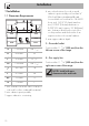
1.2 Product dimensions Overall dimensions: Location of gas and electrical connection points. A 53 mm 2 1/16" B (max) B (min) 790 mm 31 2/16" 760 mm 29 15/16" C 472 mm 18 9/16" D 57 mm 2 4/16" E 1217 mm 47 15/16" F (max) F (min) 942 mm 37 1/16" 912 mm 35 14/16" Check the location where the range is to be installed. The range should be positioned for convenient access in the kitchen. NOTE: Observe all governing codes and ordinances.
Installation An air curtain or other overhead range hood, which operates by blowing a downward airflow onto a range, shall not be used in conjunction with the gas range unless the hood and range have been designed, tested in accordance with ANSI Z21.1 and listed by an independent testing laboratory for combination use. This type of ventilation system may cause ignition and combustion problems with the gas cooking appliance resulting in personal injury or unintended operation. 1.
Installation EN 1.4 Wall attachment and anti-tip device Warning Electrical shock hazard • Use extreme caution when drilling holes into the wall or floor. There may be concealed electrical wiring located behind the wall or under the floor. • Identify the location of the electrical circuits that could be affected by the installation of the anti-tip device, then turn off power to these circuits. • Failure to follow these instructions may result in electrical shock or other personal injury.
Installation Instructions for wall mounting (primary system) 1. Assemble the fastening bracket. 3. Align the base of the fastening bracket with the ground and tighten the screws to fix the measurements. 2. Align the base of the hook on the fastening bracket with the base of the slot on the wall fastening plate. 4. Use 50 mm for the distance from the side of the appliance to the bracket holes.
Installation Instructions for floor mounting (secondary system) EN 5. Move the bracket onto the wall and mark the position of the holes to be drilled in the wall. The secondary anti-tip device is to be attached to the floor when it is not possible to install the primary system. After having positioned and leveled the appliance the bracket has to be anchored to the floor and engaged in the slots at the rear of the appliance.
Installation 2. The bracket attachment should insert into one of the central slots at the rear. 3. After having positioned and leveled the appliance, move the bracket close to the rear of the appliance and anchor it to the floor. 18 4. Lower the bracket attachment until anchoring the appliance slot, tighten the nuts previously assembled. The anti-tip device works properly only if the bracket attachment is securely anchored to the appliance.
1.5 Electrical requirements Warning Electrical shock hazard • Frame grounded by connection of grounding lead to neutral lead. If used in a mobile home or if local codes do not permit grounding through neutral, open connection and use grounding lead to ground unit in accordance with local codes. Connect neutral lead to branchcircuit neutral conductor in usual manner. • Do not use an adaptor. • Do not use an extension cord.
Installation • Wire size and connections must conform to the requirements of the National Electrical Code, NFPA 70 or the Canadian Electric Code, CSA C22.102 or latest edition and all local codes and ordinances for the kilowatt rating of the range. IMPORTANT: Observe all governing codes and ordinances.
Installation U.S. and Canada installation / 4-wire branch circuit Refer to figure, where local codes allow the connection of the ground wire from the oven to the power supply cable neutral wire (white wire): • The ground wire must be connected first; • If local codes permit, connect the green or yellow-green ground wire from the range and the white wire from the range to the power supply neutral wire (white wire).
Installation • Connect to a 50A fuse or circuit breaker. Connect to copper wire, or, if connection is made to aluminum house wiring, use UL-listed or CSA-approved connectors approved for joining aluminum and copper wiring. NOTE: Both leads coming out of the range must be connected according to the diagrams shown in figures. 1.6 Gas supply requirements Warning Explosion hazard • Use a new AGA or CSA-approved gas supply line. • Install a shut-off valve. • Securely tighten all gas connections.
Installation The appliance is shipped from the factory for use with natural gas at a pressure of 5" of water column. When checking if the regulator is working properly, the inlet pressure must be at least 1" greater than the operating (manifold) pressure above. When used with natural gas, the pressure supplied to the regulator must be between 6" and 10.5" of the water column. To convert the appliance to propane gas see "Conversion to propane gas (LPG)".
Installation Due to problems of overall dimensions at the back, screw in the pressure regulator so that it is sloped at 45° vs the wall at the back of the appliance. Shut-off valve The supply line must be fitted with an approved shut-off valve. This valve should be located in the same room as the range and should be in a location where it can be easily opened and closed. Do not block access to the shut-off valve. The valve is necessary for turning the gas to the appliance on or off.
• Natural Gas: Set pressure to 5” W.C.P. Incoming line pressure of 6” - 10 1/2” W.C.P maximum. • LP Gas: Set pressure to 10” W.C.P. Incoming line pressure 11”- 13” W.C.P. maximum. Lubricating the surface burner gas valves Over time, the surface burner gas valves may become stiff or jam. Clean them internally and relubricate. This operation must be carried out by a qualified technician.
Installation 2. Secure the backguard to the top by tightening screws. 3. Fasten the front skirting to the appliance using the previously removed screws. Installing the front skirting Installing the side skirting The front skirting must always be positioned and secured correctly on the appliance. 1. Use a screwdriver to remove the front screws undreneath the storage compartment. After installing the front skirting, the side skirting can be fastened correctly to the appliance. 1.
3. Line up the holes on the side skirting with the rear holes on the base of the appliance. 4. Secure the side kick plate with the supplied screws. 5. Repeat the operations described above for the other side skirting section. 1.7 For the installer • The plug must remain accessible after the installation is complete. Do not kink or trap the mains connection cable. • The appliance must be fitted according to the installation diagrams. • Do not attempt to turn or stress the threaded elbow on the manifold.
PAGE INTENTIONALLY LEFT BLANK