Contents 1.1 1.2 1.3 1.4 1.5 1.6 General safety instructions Identification plate Manufacturer liability Appliance purpose This user manual How to read the user manual 2 Description 2.1 2.2 2.3 2.4 2.5 General Description Cooktop Control panel Other parts Available accessories 3 Use 3.1 3.2 3.3 3.4 3.5 3.6 3.7 3.8 Cleaning the appliance Removing the door Cleaning the door glazing Removing the internal glass panes Pyrolytic cycle Extraordinary maintenance 5 Installation 5.1 5.2 5.3 5.4 5.5 5.6 5.
Instructions 1 Instructions 1.1 General safety instructions Risk of personal injury • During use the appliance becomes hot. Care should be taken to avoid touching heating elements inside the oven. • Protect your hands by wearing oven gloves when handling food inside the oven cavity. • Never try to put out a fire or flames with water: turn off the appliance and smother the flames with a fire blanket or other appropriate cover.
• Do not insert pointed metal objects (cutlery or utensils) into the slots in the appliance. • Do not pour water directly onto very hot trays. • Keep the oven door closed during cooking. • If you need to move food or at the end of cooking, open the door 5 cm for a few seconds, let the steam come out, then open it fully. • Do not open the storage compartment (if present) when the oven is on and still hot. • The items inside the storage compartment could be very hot after the oven has been used.
Instructions • Do not seat on the appliance. • During the automatic cleaning cycle, the outer door window could become hotter than normal. • Excess spillage must be removed before cleaning cycle begins. • Do not obstruct ventilation openings and heat dispersal slots. • Never leave the appliance unattended during cooking operations in which fats or oils could be released that could overheat and catch fire. Be very careful • Danger of fire - Do not store items on the cooking surface.
powders, stain removers and metallic sponges) on glass parts. • Do not wash the removable components such as the cooktop pan stands, flame-spreader crowns and burner caps in a dishwasher. • Never use the oven door to lever the appliance into place when fitting. • Avoid exerting too much pressure on the oven door when open. • Do not use the handle to lift or move the appliance. • DO NOT PLACE ARTICLES ON OR AGAINST THIS APPLIANCE. Installation • THIS APPLIANCE MUST NOT BE INSTALLED IN BOATS OR CARAVANS.
Instructions • If the electrical supply is restricted, means of all-pole disconnection must be accessible and incorporating in the fixed wiring in accordance with the wiring rules. • If this cooking range is to be connected to a new or upgraded electrical installation, then it must be connected by a supply cord fitted with: 1) An appropriate rated plug that is compatible with the socket-outlet fitted to the final sub circuit in the fixed wiring that supplies this cooker.
1.4 Appliance purpose • This appliance is intended for cooking food in the home environment. Every other use is considered improper. • This appliance is not intended to be operated by means of external timer or separate remote control system. 1.5 This user manual This user manual is an integral part of the appliance and must therefore be kept in its entirety and in an accessible place for the whole working life of the appliance. Read this user manual carefully before using the appliance. 1.
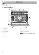
Description 2 Description 2.
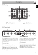
Description AUX = Auxiliary burner SR = Semi-rapid burner EN 2.2 Cooktop R = Rapid burner UR2 = Ultra rapid burner 2.3 Control panel 1 Temperature knob 3 Programmer clock This knob allows you to select the cooking temperature. Turn the knob clockwise to the required value, between the minimum and maximum setting. Useful for displaying the current time, setting programmed cooking operations and programming the minute minder timer.
Description 5 Door lock indicator light Interior lighting It comes on when the automatic (pyrolytic function) cleaning cycle is activated. The appliance interior lighting comes on: • When the door is opened • When any function is selected. 6 Cooktop burner knobs Useful for lighting and adjusting the cooktop burners. Press and turn the knobs anticlockwise to the value to light the relative burners. Turn the knobs to the zone between the maximum and minimum setting to adjust the flame.
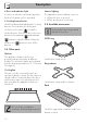
Description Rotisserie rod EN Tray rack To be placed over the top of the tray; for cooking foods which may drip. Tray Useful for cooking chicken and all foods which require uniform cooking over their entire surface. Protective cover (pyrolytic oven) Useful for collecting fat from foods placed on the rack above. Deep tray Used to cover and protect the temperature probe socket when the temperature probe is not in use. Useful for collecting fat from foods placed on the rack above.
Use 3 Use Instructions High temperature inside the oven during use Danger of burns • Keep the oven door closed during cooking. • Protect your hands wearing heat resistant gloves when moving food inside the oven. • Do not touch the heating elements inside the oven. • Do not pour water directly onto very hot trays. • Do not allow children younger than 8 years old to come near the appliance when in operation.
High temperature inside the oven during use Danger of fire or explosion • Do not spray any spray products near the oven. • Do not use or leave flammable materials near the oven or the storage compartment. • Do not use plastic kitchenware or containers when cooking food. • Do not put sealed tins or containers in the oven. • Do not leave the oven unattended during cooking operations where fats or oils could be released. • Remove all trays and racks which are not required during cooking.
Use 3.2 Using the accessories Racks and trays Racks and trays have to be inserted into the side guides until they come to a complete stop. • The mechanical safety locks that prevent the rack from being taken out accidentally have to face downwards and towards the oven back. Tray rack The tray rack has to be inserted into the tray. In this way fat can be collected separately from the food which is being cooked. Gently insert racks and trays into the oven until they come to a stop.
Rotisserie rod 1. Insert the 4 supplied bushings in the 4 corner holes of the deep tray and screw them onto the ring nuts with a suitable tool (such as a screwdriver). 2. Position the rotisserie supports in the bushings as shown in the figure below. 3. Prepare the rotisserie rod with the food using the clip forks provided. The clip forks can be tightened using the fastening screws. 4. Once you have prepared the rotisserie rod, place it on the supports.
Use 6. Insert the tip of the rod in the rotisserie motor housing on the left of the rear wall of the oven. 8. When cooking is complete, remove the tray with the rotisserie. 9. Screw on the handle provided so that you can handle the rotisserie rod more easily. 3.3 Using the cooktop These operations must be performed with the oven off and cold. 7. To activate the rotisserie, turn the function knob to the position and set the cooking temperature using the temperature knob.
Wait a few moments and repeat the operation. Keep the knob pressed in longer. In case of an accidental switching off, a safety device will be tripped, cutting off the gas supply, even if the gas cock is open. Return the knob to and wait at least 60 seconds before lighting it again. Correct positioning of the flamespreader crowns and burner caps Before lighting the cooktop burners, make sure that the flame-spreader crowns are correctly positioned in their housings with their respective burner caps.
Use 3.5 Using the oven Switching on the oven To switch on the oven: 1. Select the cooking function using the function knob. 2. Select the temperature using the temperature knob. Ensure that the programmer clock shows the cooking duration symbol , otherwise it will not be possible to turn on the oven. Press the keys and at the same time to reset the programmer clock. Preheating stage Cooking functions are always preceded by a preheating stage, which allows the appliance to heat up to cooking temperature.
Fan grill The air produced by the fan softens the strong heatwave generated by the grill, grilling perfectly even very thick foods. Perfect for large cuts of meat (e.g. pork hock). Fan assisted The operation of the fan, combined with traditional cooking, ensures consistent cooking even with complex recipes. Perfect for biscuits and cakes, even when simultaneously cooked on several levels. (For multiple-level cooking, we recommend using the 2nd and 4th shelf.
Use 3.6 Using the temperature probe High temperature of the temperature probe Danger of burns • Do not touch the rod or the tip of the probe after having used it. • Wear oven gloves or use potholders when handling the probe. Improper use Risk of damage to surfaces • Take care not to scratch or damage enamelled or chrome-plated surfaces with the tip or the plug of the temperature probe. Improper use Risk of damage to the appliance • Do not insert the probe into openings and slots on the appliance.
Use 1. Place the food on a tray. 2. Insert the tip of the probe into the food before placing it in the oven. 3. For best results, make sure that the temperature probe is placed transversely in the thickest part of the food and for least 3/4 of its length. Make sure that it does not touch the tray underneath and that it does not protrude from the food. In order for the probe to measure the core temperature of the food precisely, its tip must not be in contact with bones or fat.
Use 6. Use the and buttons to regulate the target temperature to a value between the minimum and a maximum. • Minimum target temperature: corresponds to the instantaneous temperature measured by the probe plus 2°C. • Maximum target temperature: 99°C 7. Wait for a few seconds and then press the button to display the instantaneous temperature measured by the probe. Cooking will now continue until the instantaneous temperature measured by the probe is the same as the target temperature set by the user.
4. Remove the food from the oven. 5. Make sure that the protective cover is properly closed. 3.7 Cooking advice General advice • Use a fan assisted function to achieve consistent cooking at several levels. • It is not possible to shorten cooking times by increasing the temperature (the food could be overcooked on the outside and undercooked on the inside). Advice for cooking meat • Cooking times vary according to the thickness and quality of the food and to consumer taste.
Use Advice for defrosting and proving • Place frozen foods without their packaging in a lidless container on the first shelf of the oven. • Avoid overlapping the food. • To defrost meat, use the rack placed on the second level and a tray on the first level. In this way, the liquid from the defrosting food drains away from the food. • The most delicate parts can be covered with aluminium foil. • For successful proving, a container of water should be placed in the bottom of the oven.
Setting the time If the time is not set, the oven will not switch on. On the first use, or after a power failure, the digits will be flashing on the appliance’s display. Timed cooking Timed cooking is the function which allows a cooking operation to be started and then ended after a specific length of time set by the user. 1. Keep the clock key 1. Hold down the clock key for two seconds. The dot between the hours and the minutes flashes. 2. The time can be set using the value 2.
Use 7. Press the clock key programmer clock. to reset the It is not possible to set a cooking time of more than 10 hours. To reset the set program, hold down the value increase and value decrease keys at the same time and switch off the oven manually. 4. Use the or key to set the required minutes. (For example, 1 hour) 5. Press the menu key will appear on the display in sequence with the pre-set cooking duration added to the current time. (For example, the current time is 18:30). 6.
10. Return the function and temperature knobs to 0. 11. To turn off the buzzer just press any key of the programmer clock. 12. Press the and keys at the same time to reset the set program. It is not possible to set a cooking time of more than 10 hours. It is not possible to set a programmed cooking time of more than 24 hours. After the setting, hold down the menu key for 2 seconds to display the cooking time left. Press the menu key again.
Use Modifying the set data 1. Press the clock key . 2. Use the value increase decrease minutes. and value keys to set the required Deleting the set data 1. Press the clock key . 2. Hold down the value increase and value decrease keys at the same time. 3. Then switch off the oven manually if cooking is in progress. Selecting the buzzer The buzzer can have 3 tones. 1. Hold down the value increase value decrease time. 2. Press the clock key keys at the same . 3.
Use EN Cooking information table Lasagne Pasta bake 3-4 3-4 Convection Convection Runner position from the bottom 1 1 Roast veal Pork Sausages Roast beef Roast rabbit Turkey breast Roast pork neck Roast chicken 2 2 1.5 1 1.5 3 2-3 1.
Use Probe-cooking information table Type and cut of meat Target temperature (°C) Beef Roast beef: rare 50 - 53 Roast beef: medium 55 - 58 Roast beef: well done 65 - 70 Rib of beef: rare* 50 Rib of beef: medium* 58 Rib of beef: well done* 70 Pork Roast loin 80 - 85 Shoulder 80 - 85 Sausages** 75 - 80 Veal roast 75 - 80 Whole chicken 80 - 85 Whole turkey 80 - 85 Roast turkey (whole or breast) 80 - 85 Veal Poultry Lamb Leg of lamb with bone (rare) 65 Leg of lamb with bone (well d
Cleaning and maintenance Instructions Improper use Risk of damage to surfaces • Do not use steam jets to clean the appliance. • Do not use cleaning products containing chlorine, ammonia or bleach on steel parts or parts with metallic finishes on the surface (e.g. anodizing, nickel- or chromium-plating). • Do not use abrasive or corrosive detergents (e.g. scouring powders, stain removers and metallic sponges) on glass parts. • Do not use rough or abrasive materials or sharp metal scrapers.
Cleaning and maintenance Cleaning the igniters and thermocouples 4.2 Removing the door • If necessary, clean the igniters and thermocouples with a damp cloth. • If there is any dry residue, remove it with a toothpick or needle. For easier cleaning, the door can be removed and placed on a tea towel. To remove the door proceed as follows: 1. Open the door completely and insert two pins into the holes on the hinges indicated in the figure.
3. To reassemble the door, put the hinges in the relevant slots in the oven, making sure that grooved sections A are resting completely in the slots. Lower the door and once it is in place remove the pins from the holes in the hinges. 4.4 Removing the internal glass panes For easier cleaning the door internal glass panes can be disassembled. 1. Remove the internal glass pane by pulling the rear part gently upwards, following the movement indicated by the arrows (1). 2.
Cleaning and maintenance 4. Clean the external glass pane and the panes previously removed. Use absorbent kitchen roll. In case of stubborn dirt, wash with a damp sponge and neutral detergent. 5. Refit the panes in the reverse order in which they were removed. 6. Reposition the internal glass pane. Take care to centre and insert the 4 pins into their housings in the oven door by applying slight pressure.
Manually disengaging the door lock lever 1. Move the door lock lever to the right until it stops. Improper use Danger of burns • The following must always be carried out when the appliance is cold and switched off. • Never attempt to disengage the door lock lever manually during the pyrolytic cycle. The door lock lever is located in the first slot on the left under the control panel, in the upper part of the front of the oven. (as seen from above) 2. Release the door lock lever gently.
Cleaning and maintenance 4.5 Pyrolytic cycle The pyrolytic function consists of an automatic high-temperature cleaning procedure which causes dirt to dissolve. Thanks to this process, it is possible to clean the oven cavity very easily. Improper use Risk of damage to surfaces • Remove any food residues or large spills from previous cooking operations from the oven cavity. Preliminary operations Before starting the pyrolytic cycle: • Clean the internal glass panel following the usual cleaning instructions.
Cleaning and maintenance Setting of programmed pyrolytic cycle It is possible to program the pyrolytic cycle start time like all other cooking functions. 1. After having started the pyrolysis cycle (see “Setting up the pyrolytic function”), press and hold the button for 2 seconds. 2. Continue to press the button until 4. Press the settings. button to confirm the EN 7. The door remains locked as long as the temperature inside the oven returns to safety levels. 8.
Cleaning and maintenance 4.6 Extraordinary maintenance 4. Slide out and remove the light bulb. Replacing the oven light bulb Live parts Danger of electrocution • Unplug the appliance. The oven is fitted with two 40W light bulbs. 1. Completely remove all accessories from inside the oven. 2. Remove the racks/trays support frames. 3. Remove the bulb cover using a tool (e.g. a screwdriver). Do not touch the halogen light bulb directly with your fingers, but wrap it in insulating material. 5.
Cleaning and maintenance EN What to do if... The appliance does not work. • The circuit breaker is faulty: look in the fuse box and check that the circuit breaker is in working order. • Power cut: check whether the kitchen light works. The gas burner does not ignite. • Power cut or damp ignition plugs: light the gas burner with a gas lighter or a match. The oven does not heat up. • Faulty fuse: check and, if required, replace the circuit breaker. • The function knob has not been set: set the function knob.
Installation 5 Installation 5.1 Minimum clearance to combustible surfaces Freestanding cooker 5.2 Gas connection Gas leak Danger of explosion A 600 mm (Overhead) measured from the highest part of the highest burner and 750 mm for an exhaust fan. B 200 mm (Vertical combustible surface) measured form the edge of the nearest burner. C 10 mm (Horizontal combustible surface) below the hob. Refer to AS/NZS 5601 (Protection of a combustible surface) if the above minimum clearances cannot be achieved.
A test point (for checking the gas pressure) is supplied as a separate fitting in the case of ULPG (propane) appliances. Connection of the appliance to the gas supply must be in accordance with the requirements of AS5601. A ½” BSP connector at the inlet is recommended and the gas supply line to the appliance must be of adequate length to allow sufficient withdrawal of appliance for service or disconnection and be: 1. annealed copper pipe or; 2.
Installation Connection to liquid gas Use a pressure regulator and make the connection on the gas cylinder following the guidelines set out in the regulations in force. Make sure that the supply pressure complies with the values indicated in section “ Burner and nozzle characteristics table”. Room ventilation The room containing the appliance should have a permanent air supply in accordance with the standards in force.
5.3 Adaptation to different types of gas Adjusting the minimum setting for natural gas In case of operation with other types of gas, the burner nozzles must be changed and the minimum flame adjusted on the gas cocks. Light the burner and turn it to the minimum position. Extract the gas cock knob and turn the adjustment screw next to the cock rod (depending on the model) until the correct minimum flame is achieved. Refit the knob and verify that the burner flame is stable.
Installation Lubrication of gas cocks Over time the gas cocks may become difficult to turn and get blocked. Clean them internally and replace the lubrication grease. The greasing of the gas cocks should be performed by authorised persons. Burner and nozzle characteristics table 1 ULPG 2.75 kPa AUX SR R UR2 Nominal gas consumption (MJ/h) Injector (1/100 mm) 4.0 54 6.5 68 10.8 88 15.2 105 2 NG 1.0 kPA AUX SR R UR2 Nominal gas consumption (MJ/h) Injector (1/100 mm) 4.5 90 7.
5.4 Positioning Heavy appliance Danger of crush injuries • Place the appliance into the piece of furniture with the aid of a second person. Pressure on the open door Risk of damages to the appliance • When positioning the appliance during installation, do not use the door handle to lift up or move this appliance. • Never use the oven door to lever the appliance into place when fitting. • Avoid exerting too much pressure on the oven door when open.
Installation Positioning and levelling Heavy appliance Risk of damage to the appliance • Insert the front feet first and then the rear ones. • After making the gas and electrical connections, screw on the four feet supplied with the appliance. B - Class 2 subclass 1 (Built-in appliance) The appliance must sit level on the floor to ensure stability. • Screw or unscrew the bottom part of the foot until the appliance is stable and level on the floor.
Installation The front plinth must always be positioned and secured correctly on the appliance. 1. Use a screwdriver to remove the front screws under the storage compartment door. 2. Align the front plinth with the corresponding holes on the appliance. 3. Fasten the front plinth using the screws that were previously removed. Fastening to the wall EN Installing the front plinth The anti-tip devices must be installed in order to prevent the appliance tipping over. 1.
Installation 3. Assemble the fastening bracket. 4. Align the base of the hook on the fastening bracket with the base of the slot on the wall fastening plate. 50 5. Align the base of the fastening bracket with the ground and tighten the screws to fix the measurements. 6. Use 50 mm for the distance from the side of the appliance to the bracket holes.
7. Move the bracket onto the wall and mark the position of the holes to be drilled in the wall. Wall fixing 8. After drilling the holes in the wall, use wall plugs and screws to fasten the bracket to the wall. 9. Push the cooker towards the wall, and at the same time, insert the bracket in the plate fastened to the rear of the appliance. 2. Attach the chain to the cooker with the screw just removed. EN Installation 1. Turn the screw placed behind the cooktop near the gas connection. 3.
Installation 4. Mark the wall in the position where the hole is to be drilled. Assembling the upstand The upstand provided is an integral part of the product. It must be fastened to the appliance prior to installation. The upstand must always be positioned and secured correctly on the appliance. 1. Loosen the two bolts on the back of the cooktop using a screwdriver. 5. Drill the hole and insert a wall plug. 6. Attach the chain and push the appliance to the wall. 2. Place the upstand on the worktop.
Installation 4. Secure the upstand to the cooktop by tightening the 2 screws previously loosened. 5.5 Electrical connection EN 3. Clip the tongues of the upstand to the ventilation slot of the cooktop (A). Power voltage Danger of electrocution • Have the electrical connection performed by authorised persons. • Use personal protective equipment. • The appliance must be connected to earth in compliance with electrical system safety standards. • Disconnect the mains supply.
Installation • 220-240 V 3~ 5.6 Access to the terminal board Access via the plate 4 x 2.5 mm² four-pole cable. • 220-240 V 1N~ To connect the power supply cable, access to the terminal board on the rear cover: 1. Remove the screws securing the lid to the rear cover. 3 x 2.5 mm² three-pole cable. • 380-415 V 2N~ 2. Slightly turn the lid and remove it from its housing. 4 x 2.5 mm² four-pole cable. • 380-415 V 3N~ 5 x 1.5 mm² five-pole cable.
Installation Access via the rear casing EN 3. Install the power supply cable. To connect the power cable, remove the fastening screws on the rear casing as shown in the figure. Loosen the cable fastener screw before installing the power supply cable. 4. At the end, reposition the lid on the rear cover and secure it with the previously removed screws. Fixed connection Fit the power line with an omnipolar circuit breaker in compliance with installation regulations.
Installation 5.7 For the installer • The plug must remain accessible after the installation is complete. Do not kink or trap the mains connection cable. • The appliance must be fitted according to the installation diagrams. • Do not attempt to turn or stress the threaded elbow on the manifold. You risk damage to this part of the appliance which may void the manufacturer’s warranty. • Before leaving check all connections for gas leaks with soap and water. DO NOT use a naked flame for detecting leaks.