Contents 1.1 1.2 1.3 1.4 1.5 1.6 General safety instructions Identification plate Manufacturer liability Appliance purpose This user manual How to read the user manual 2 Description 2.1 2.2 2.3 2.4 2.5 General Description Cooktop Control panel Other parts Available accessories 3 Use 3.1 3.2 3.3 3.4 3.5 3.6 3.7 Cleaning the appliance Removing the door Cleaning the door glazing Removing the internal glass panes Pyrolytic cycle Extraordinary maintenance 5 Installation 5.1 5.2 5.3 5.4 5.5 5.6 5.
Instructions 1 Instructions 1.1 General safety instructions Risk of personal injury • During use the appliance becomes hot. Care should be taken to avoid touching heating elements inside the oven. • Protect your hands by wearing oven gloves when handling food inside the oven cavity. • Never try to put out a fire or flames with water: turn off the appliance and smother the flames with a fire blanket or other appropriate cover.
• When in use, do not place metal objects, such as dishes or cutlery, on the surface of the cooktop as they may overheat. • Do not insert pointed metal objects (cutlery or utensils) into the slots in the appliance. • Do not pour water directly onto very hot trays. • Keep the oven door closed during cooking. • If you need to move food or at the end of cooking, open the door 5 cm for a few seconds, let the steam come out, then open it fully.
Instructions Risk of damaging the appliance • Do not use abrasive or corrosive detergents (e.g. scouring powders, stain removers and metallic sponges) on glass parts. • Use wooden or plastic utensils. • Racks and trays must be inserted as far as they will go into the side guides. The mechanical safety locks that prevent them from being removed must face downwards and towards the back of the oven cavity. • Do not seat on the appliance. • Do not use steam jets to clean the appliance.
• Do not use steam jets to clean the appliance. • Do not use harsh abrasive cleaners or sharp metal scrapers to clean the oven glass door since they can scratch the surface, which may result in shattering of the glass. • Do not use cleaning products containing chlorine, ammonia or bleach on steel parts or parts with metallic surface finishes (e.g. anodizing, nickel- or chromiumplating). • Do not use abrasive or corrosive detergents (e.g. scouring powders, stain removers and metallic sponges) on glass parts.
Instructions • After carrying out any operation, check that the tightening torque of gas connections is between 10 Nm and 15 Nm. • At the end of the installation, check for any leaks with a soapy solution, never with a flame. • Have the electrical connection performed by authorised persons. • The appliance must be connected to earth in compliance with electrical system safety standards.
1.3 Manufacturer liability • The manufacturer declines all liability for damage to persons or property caused by: • use of the appliance other than the one envisaged; • non-observance of the user manual provisions; • tampering with any part of the appliance; • use of non-original spare parts. 1.4 Appliance purpose • This appliance is intended for cooking food in the home environment. Every other use is considered improper.
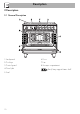
Description 2 Description 2.
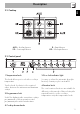
Description AUX = Auxiliary burner SR = Semi-rapid burner EN 2.2 Cooktop R = Rapid burner UR = Ultra rapid burner 2.3 Control panel 1 Temperature knob 3 Door lock indicator light This knob allows you to select the cooking temperature. It comes on when the automatic (pyrolytic function) cleaning cycle is activated. Turn the knob clockwise to the required value, between the minimum and maximum setting.
Description Useful for lighting and adjusting the cooktop burners. Press and turn the knobs anti-clockwise to the value to light the relative burners. Turn the knobs to the zone between the maximum and minimum setting to adjust the flame. Return the knobs to the off the burners. position to turn 2.4 Other parts Interior lighting The appliance interior lighting comes on: • When the door is opened • When any function is selected. 2.5 Available accessories Some models are not provided with all accessories.
Description Tray Useful for supporting containers with food during cooking. Useful for collecting fat from foods placed on the rack above. Tray rack Deep tray To be placed over the top of the oven tray; for cooking foods which may drip. EN Rack Useful for collecting fat from foods placed on the rack above. The accessories intended to come into contact with food are made of materials that comply with the provisions of current legislation.
Use 3 Use Instructions High temperature inside the oven during use Danger of burns • Keep the oven door closed during cooking. • Protect your hands wearing heat resistant gloves when moving food inside the oven. • Do not touch the heating elements inside the oven. • Do not pour water directly onto very hot trays. • Do not allow children younger than 8 years old to come near the appliance when in operation.
High temperature inside the oven during use Danger of fire or explosion • Do not spray any spray products near the oven. • Do not use or leave flammable materials near the oven or the storage compartment. • Do not use plastic kitchenware or containers when cooking food. • Do not put sealed tins or containers in the oven. • Do not leave the oven unattended during cooking operations where fats or oils could be released. • Remove all trays and racks which are not required during cooking.
Use 3.2 Using the accessories Ring reducers Racks and trays The ring reducers have to be placed on the cooktop grids. Make sure they are placed properly. Racks and trays have to be inserted into the side guides until they come to a complete stop. • The mechanical safety locks that prevent the rack from being taken out accidentally have to face downwards and towards the oven back. Gently insert racks and trays into the oven until they come to a stop.
Use All the appliance's control and monitoring devices are located together on the front panel. The burner controlled by each knob is shown next to the knob. The appliance is equipped with an electronic ignition device. Simply press the knob and turn it anticlockwise to the maximum flame symbol, until the burner lights. If the burner does not light in the first 15 seconds, turn the knob to and wait 60 seconds before trying again.
Use 3.4 Using the storage compartment Preheating stage The storage compartment is at the bottom of the cooker. To open it, pull the handle towards you. It can be used to store cookware or metallic objects necessary when using the appliance. Cooking functions are always preceded by a preheating stage, which allows the appliance to heat up to cooking temperature. The indicator light comes on to indicate that the oven is heating up.
Small grill Using only the heat released from the central element, this function enables small portions of meat and fish to be grilled for making kebabs, toasted sandwiches and all types of grilled vegetable side dishes. Grill The heat coming from the grill element gives perfect grilling results above all for thin and medium thickness meat and, in combination with the rotisserie (where fitted), gives the food an even browning at the end of cooking. Perfect for sausages, spare ribs and bacon.
Use Cooking (and preheating) times are longer with the ECO function. When using the ECO function, avoid opening the door during cooking. 3.6 Cooking advice General advice • Use a fan assisted function to achieve consistent cooking at several levels. • It is not possible to shorten cooking times by increasing the temperature (the food could be overcooked on the outside and undercooked on the inside).
Use To save energy • Stop cooking a few minutes before the time normally used. Cooking will continue for the remaining minutes with the heat which has accumulated inside the oven. • Reduce any opening of the door to a minimum to avoid heat dispersal. • Keep the inside of the appliance clean at all times. 3.7 Programmer clock EN Advice for defrosting and proving • Place frozen foods without their packaging in a lidless container on the first shelf of the oven. • Avoid overlapping the food.
Use Setting the time If the time is not set, the oven will not switch on. On the first use, or after a power failure, the digits will be flashing on the appliance’s display. 1. Press the keys and at the same time. The dot between the hours and the minutes flashes. 2. The time can be set using the key or . Keep the key pressed in to increase or decrease rapidly. 3. Press the key or wait 5 seconds. The dot between the hours and the minutes stops flashing. 4.
Use It is not possible to set a cooking time of more than 10 hours. After the setting, to display the cooking time left press the key . 3. Use the key or to set the required minutes. 4. Wait approx. 5 seconds without pressing any key in order for the function to activate. The current time and the symbols and will appear on the display. 5. At the end of cooking the heating elements will be deactivated.
Use Minute minder timer The minute minder timer does not stop the cooking operation but rather informs the user when the set time has run out. The minute minder timer can be activated at any time. 1. Press the key . The display shows the digits and the indicator light flashing between the hours and the minutes. 2. Use the key or to set the required minutes. 3. Wait approx. 5 seconds without pressing any key to finish setting the minute minder. The current time and the symbols display.
Use EN Cooking information table Lasagne Pasta bake 3-4 3-4 Convection Convection Runner position from the bottom 1 1 Roast veal Pork Sausages Roast beef Roast rabbit Turkey breast Roast pork neck Roast chicken 2 2 1.5 1 1.5 3 2-3 1.
Cleaning and maintenance 4 Cleaning and maintenance Instructions Improper use Risk of damage to surfaces • Do not use steam jets to clean the appliance. • Do not use cleaning products containing chlorine, ammonia or bleach on steel parts or parts with metallic finishes on the surface (e.g. anodizing, nickel- or chromium-plating). • Do not use abrasive or corrosive detergents (e.g. scouring powders, stain removers and metallic sponges) on glass parts.
Cleaning the igniters and thermocouples 4.2 Removing the door • If necessary, clean the igniters and thermocouples with a damp cloth. • If there is any dry residue, remove it with a toothpick or needle. For easier cleaning, the door can be removed and placed on a tea towel. To remove the door proceed as follows: 1. Open the door completely and insert two pins into the holes on the hinges indicated in the figure. Recommendations for cleaning the oven cavity 2.
Cleaning and maintenance 3. To reassemble the door, put the hinges in the relevant slots in the oven, making sure that grooved sections A are resting completely in the slots. Lower the door and once it is in place remove the pins from the holes in the hinges. 4.4 Removing the internal glass panes For easier cleaning the door internal glass panes can be disassembled. 1. Remove the internal glass pane by pulling the rear part gently upwards, following the movement indicated by the arrows (1). 2.
4. Clean the external glass pane and the panes previously removed. Use absorbent kitchen roll. In case of stubborn dirt, wash with a damp sponge and neutral detergent. Removing racks/trays support frames Removing the guide frames enables the sides to be cleaned more easily. This operation should be performed each time the automatic cleaning cycle is used (on some models only).
Cleaning and maintenance Manually disengaging the door lock lever 1. Move the door lock lever to the right until it stops. Improper use Danger of burns • The following must always be carried out when the appliance is cold and switched off. • Never attempt to disengage the door lock lever manually during the pyrolytic cycle. The door lock lever is located in the first slot on the left under the control panel, in the upper part of the front of the oven. (as seen from above) 2.
Cleaning and maintenance The pyrolytic function consists of an automatic high-temperature cleaning procedure which causes dirt to dissolve. Thanks to this process, it is possible to clean the oven cavity very easily. Improper use Risk of damage to surfaces • Remove any food residues or large spills from previous cooking operations from the oven cavity. Preliminary operations Before starting the pyrolytic cycle: • Clean the internal glass panel following the usual cleaning instructions.
Cleaning and maintenance 7. At the end of the pyrolytic cycle, the door remains locked as long as the temperature inside the oven returns to safety levels. 8. At the end of the pyrolytic cycle, wait for the oven to cool down and collect the residues deposited inside with a damp microfibre cloth. 4.6 Extraordinary maintenance Removing and installing the oven seal To remove the oven seal: • Unhook the clips in the 4 corners and in the centre, then pull the oven seal.
Cleaning and maintenance 4. Slide out and remove the light bulb. EN Replacing the oven light bulb Live parts Danger of electrocution • Unplug the appliance. The oven is fitted with two 40W light bulbs. 1. Completely remove all accessories from inside the oven. 2. Remove the racks/trays support frames. 3. Remove the bulb cover using a tool (e.g. a screwdriver). Pay attention not to scratch the oven cavity enamel.
Cleaning and maintenance What to do if... The appliance does not work. • The circuit breaker is faulty: look in the fuse box and check that the circuit breaker is in working order. • Power cut: check whether the kitchen light works. The gas burner does not ignite. • Power cut or damp ignition plugs: light the gas burner with a gas lighter or a match. The oven does not heat up. • Faulty fuse: check and, if required, replace the circuit breaker. • The function knob has not been set: set the function knob.
Installation EN 5 Installation 5.1 Minimum clearance to combustible surfaces Freestanding cooker 5.2 Gas connection Gas leak Danger of explosion A 600 mm (Overhead) measured from the highest part of the highest burner and 750 mm for an exhaust fan. B 200 mm (Vertical combustible surface) measured form the edge of the nearest burner. C 10 mm (Horizontal combustible surface) below the hob. • After carrying out any operation, check that the tightening torque of gas connections is between 10 Nm and 15 Nm.
Installation General informations This appliance is suitable for installation with Natural Gas or ULPG (propane/butane). Refer to “Burner and nozzle characteristics table” section for the relevant burner pressure and appropriate injector sizes. When the appliance is to be connected to Natural Gas then the pressure regulator must be fitted to the gas inlet. A test point (for checking the gas pressure) is supplied either with the regulator or as a separate fitting in the case of ULPG (propane) appliances.
Installation EN Connection to liquid gas Use a pressure regulator and make the connection on the gas cylinder following the guidelines set out in the regulations in force. Make sure that the supply pressure complies with the values indicated in section “ Burner and nozzle characteristics table”. Room ventilation The room containing the appliance should have a permanent air supply in accordance with the standards in force.
Installation 5.3 Adaptation to different types of gas In case of operation with other types of gas, the burner nozzles must be changed and the minimum flame adjusted on the gas cocks. Turn the knob rapidly from the maximum to the minimum setting: the flame should not go out. Repeat the operation on all gas cocks. Replacing nozzles 1. Remove the pan stands, burner caps and flame-spreader crowns to access the burner casings. 2.
Installation 1 ULPG 2.75 kPa AUX SR R UR Nominal gas consumption (MJ/h) Injector (1/100 mm) 4.0 54 7.0 68 11.0 88 15.0 105 2 NG 1.0 kPA AUX SR R UR Nominal gas consumption (MJ/h) Injector (1/100 mm) 4.0 90 7.0 120 12.0 155 13.0 165 Overall dimensions Location of gas and electrical connection points. EN Burner and nozzle characteristics table 5.4 Positioning Heavy appliance Danger of crush injuries • Place the appliance into the piece of furniture with the aid of a second person.
Installation General information This appliance may be installed next to walls, one of which must be higher than the worktop, at a minimum distance of 50 mm from the side of the appliance, as shown in figures A and C relative to the installation classes. Any wall units positioned above the worktop must be at a minimum distance of at least 600 mm. If a hood is installed above the cooktop, refer to the hood instruction manual to ensure the correct clearance is left.
Installation Heavy appliance Risk of damage to the appliance • Insert the front feet first and then the rear ones. Fastening to the wall EN Positioning and levelling The anti-tip devices must be installed in order to prevent the appliance tipping over. 1. Screw the wall fastening plate to the rear of the appliance. • After making the gas and electrical connections, screw on the four feet supplied with the appliance. The appliance must sit level on the floor to ensure stability.
Installation 3. Assemble the fastening bracket. 4. Align the base of the hook on the fastening bracket with the base of the slot on the wall fastening plate. 42 5. Align the base of the fastening bracket with the ground and tighten the screws to fix the measurements. 6. Use 50 mm for the distance from the side of the appliance to the bracket holes.
Installation Wall fixing 8. After drilling the holes in the wall, use wall plugs and screws to fasten the bracket to the wall. 9. Push the cooker towards the wall, and at the same time, insert the bracket in the plate fastened to the rear of the appliance. 2. Attach the chain to the cooker with the screw just removed. EN 7. Move the bracket onto the wall and mark the position of the holes to be drilled in the wall. 1. Turn the screw placed behind the cooktop near the gas connection. 3.
Installation 4. Mark the wall in the position where the hole is to be drilled. Assembling the upstand The upstand provided is an integral part of the product. It must be fastened to the appliance prior to installation. The upstand must always be positioned and secured correctly on the appliance. 1. Loosen the two bolts on the back of the cooktop using a screwdriver. 5. Drill the hole and insert a wall plug. 6. Attach the chain and push the appliance to the wall. 2. Place the upstand on the worktop.
Installation 4. Secure the upstand to the cooktop by tightening the 2 screws previously loosened. 5.5 Electrical connection EN 3. Clip the tongues of the upstand to the ventilation slot of the cooktop. (A) Power voltage Danger of electrocution • Have the electrical connection performed by authorised persons. • Use personal protective equipment. • The appliance must be connected to earth in compliance with electrical system safety standards. • Disconnect the mains supply.
Installation The appliance can work in the following modes: • 220-240 V 2~ The aforementioned power cables are sized taking into account the coincidence factor (in compliance with standard EN 60335-2-6). 5.6 Access to the terminal board (depending on the model) 3 x 2.5 mm² three-pole cable. • 220-240 V 3~ Access via the plate To connect the power supply cable, access to the terminal board on the rear cover: 1. Remove the screws securing the lid to the rear cover. 4 x 2.5 mm² four-pole cable.
Installation Access via the rear casing EN 3. Install the power supply cable. To connect the power cable, remove the fastening screws on the rear casing as shown in the figure. Loosen the cable fastener screw before installing the power supply cable. 4. At the end, reposition the lid on the rear cover and secure it with the previously removed screws. Fixed connection Fit the power line with an omnipolar circuit breaker in compliance with installation regulations.
Installation 5.7 For the installer • The plug must remain accessible after the installation is complete. Do not kink or trap the mains connection cable. • The appliance must be fitted according to the installation diagrams. • Do not attempt to turn or stress the threaded elbow on the manifold. You risk damage to this part of the appliance which may void the manufacturer’s warranty. • Before leaving check all connections for gas leaks with soap and water. DO NOT use a naked flame for detecting leaks.