Libretto di Istruzioni Instructions Manual Manuel d’Instructions Bedienungsanleitung Gebruiksaanwijzing Manual de instrucciones Manual de Instruções KIV90X
INDICE IT CONSIGLI E SUGGERIMENTI ..............................................................................................................................................4 CARATTERISTICHE ..............................................................................................................................................................5 INSTALLAZIONE...............................................................................................................................................
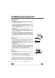
RECOMMENDATIONS AND SUGGESTIONS The Instructions for Use apply to several versions of this appliance. Accordingly, you may find descriptions of individual features that do not apply to your specific appliance. INSTALLATION • The manufacturer will not be held liable for any damages resulting from incorrect or improper installation.
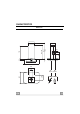
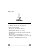
CHARACTERISTICS 90 132 70 36 310 Max 1070 700 Min 780 Dimensions 350 EN Min. Min.
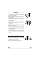
Components Ref. 1 2 2.1 2.2 7.1 Q.ty 1 1 1 1 1 7.1a 7.1b 8a 8b 9 14.1 15 24 25 26 27 1 1 1 1 1 1 1 1 Ref. 11 12c 12e 12f 12g 12h 12q 21 22 23 2 1 Q.
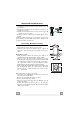
INSTALLATION Drilling the Ceiling/shelf and fixing the frame DRILLING THE CEILING/SHELF • Use a plumb line to mark the centre of the hob on the ceiling/support shelf. • Place the drilling template 21 provided on the ceiling/support shelf, making sure that the template is in the correct position by lining up the axes of the template with those of the hob. • Mark the centres of the holes in the template.
Fixing the frame • Loosen the two screws fastening the lower chimney and remove this from the lower frame. • Loosen the two screws fastening the upper chimney and remove this from the upper frame. If you wish to adjust the height of the frame, proceed as follows: • Unfasten the metric screws joining the two columns, located at the sides of the frame. • Adjust the frame to the height required, then refit all the screws removed as above.
RECIRCULATION VERSION AIR OUTLET • Assemble the two halves of the hood body extension piece 14 (if necessary). • Push fit the assembled hood body extension piece 14 onto the air outlet (if necessary). • Push fit connection 15 onto the hood body extension piece 14 or directly onto the hood body. • Insert the connection extension pieces laterally 14.1 in connection 15.
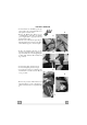
ELECTRICAL CONNECTION • Connect the Hood to the Mains power supply, inserting a two-pole Switch with a contact aperture of at least 3 mm. • Remove the Metal grease filters (see par. on “Maintenance”) and make sure that the power supply Cable is properly inserted in the Suction fan socket. • Take the wires indicated in fig.1 and pass them through the slot formed on the galvanized diffuser support, as shown in fig.2.
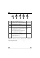
USE L L1 L2 L3 L4 T1 T2 T3 T4 Control panel Button Function Led L Press briefly to turn the lighting system on and off. Press and hold for approx. 2 seconds to turn the lighting system on and off at reduced intensity. T1 Turn the suction motor on and off at speed one. If the filter saturation alarm is on, this resets it. On. T2 Turn the suction motor on at speed two. If the filter saturation alarm is on, this resets it. On. T3 On.
MAINTENANCE Metal grease filters These can also be washed in the dishwasher, and need to be cleaned when all the command LEDs light up in a continuous manner or at least once every 2 months use, or more frequently if use is particularly intensive. Resetting the alarm signal • Press any of the buttons except the Light button. Cleaning the Filters • Remove the Filters one at a time, pushing them towards the back of the unit and at the same time pulling downward.
Activated Charcoal Filter (Recirculation Version) • This cannot be washed or regenerated, and must be changed when all the command LEDs start to flash, or at least once every 4 months. Activating the alarm signal • In Recirculation Version Hoods, the Filter Saturation Alarm must be activated on installation or at a later date.