Instructions Manual Manual de instrucciones Manual de Instruções KSE90XT
INDEX EN RECOMMENDATIONS AND SUGGESTIONS ..................................................................................................................... 3 CHARACTERISTICS ............................................................................................................................................................. 4 INSTALLATION.................................................................................................................................................................
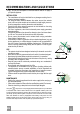
RECOMMENDATIONS AND SUGGESTIONS The Instructions for Use apply to several versions of this appliance. Accordingly, you may find descriptions of individual features that do not apply to your specific appliance. INSTALLATION • The manufacturer will not be held liable for any damages resulting from incorrect or improper installation.
CHARACTERISTICS 314 90 max. 1055 132 60 259 740 min. 740 Dimensions Min. Min. 500mm 650mm 300 260 490 108 150 Components Q.ty Product Components 1 Hood Body, complete with: Controls, Light, Blower, Filters 2 1 Telescopic Chimney comprising: 2.1 1 Upper Section 2.2 1 Lower Section 8a 1 Right Air Outlet Grill 8b 1 Left Air Outlet Grill 9 1 Reducer Flange ø 150-120 mm 14.1 2 Air Outlet Connection Extension 15 1 Air Outlet Connection Ref. Q.ty Installation Components 7.2.
INSTALLATION 1÷2 Wall drilling and bracket fixing 650 min. 12a 116 116 320 11 X 7.2.1 Wall marking: • Draw a vertical line on the supporting wall up to the ceiling, or as high as practical, at the centre of the area in which the hood will be installed. • Draw a horizontal line at 650 mm above the hob. Place bracket 7.2.1 on the wall as shown about 1-2 mm from the ceiling or upper limit aligning the centre (notch) with the vertical reference line.
Mounting the hood body • Before attaching the hood body, tighten the two screws Vr located on the hood body mounting points. • Hook the hood body onto the screws 12a. • Fully tighten the support screws 12a. • Adjust the screws Vr to level the hood body. Vr 12a Connections DUCTED VERSION AIR EXHAUST SYSTEM When installing the ducted version, connect the hood to the chimney using either a flexible or rigid pipe ø 150 or 120 mm, the choice of which is left to the installer.
ELECTRICAL CONNECTION • Connect the hood to the mains through a two-pole switch having a contact gap of at least 3 mm. • Remove the grease filters (see paragraph Maintenance) being sure that the connector of the feeding cable is correctly inserted in the socket placed on the side of the fan. 7.2.1 Chimney assembly Upper chimney section • Slightly widen the two sides of the upper chimney and hook them behind the brackets 7.2.1, making sure that they are properly housed.
USE L S V1 V2 V3 L Ɉɫɜɟɬʂɟʃɟ ɍɤʂɭɱɭʁɟ ɢ ɢɫɤʂɭɱɭʁɟ ɫɢʁɚɥɢɰɟ. S LED V1 Ɇɨɬɨɪ V2 V3 EN LED ɭɤʂɭɱɟɧɨɝ ɦɨɬɨɪɚ. ɍɤʂɭɱɭʁɟ ɢ ɢɫɤʂɭɱɭʁɟ ɦɨɬɨɪ ɚɫɩɢɪɚɬɨɪɚ ɧɚʁɦɚʃɨɦ ɛɪɡɢɧɨɦ. Ʉɨɪɢɫɬɢ ɫɟ ɡɚ ɧɟɩɪɟɤɢɞɚɧ ɢ ɧɟɱɭʁɚɧ ɩɪɨɬɨɤ ɜɚɡɞɭɯɚ ɭ ɫɥɭɱɚʁɭ ɦɚɥɟ ɤɨɥɢɱɢɧɟ ɤɭɯɢʃɫɤɢɯ ɢɫɩɚɪɟʃɚ. Ȼɪɡɢɧɚ ɋɪɟɞʃɚ ɛɪɡɢɧɚ – ɩɨɝɨɞɧɚ ɡɚ ɜɟʄɢɧɭ ɪɚɞɧɢɯ ɭɫɥɨɜɚ, ɩɪɭɠɚ ɨɩɬɢɦɚɥɚɧ ɨɞɧɨɫ ɤɨɥɢɱɢɧɟ ɜɚɡɞɭɯɚ ɢ ɛɭɤɟ. ɂɧɬɟɧɡɢɜɧɨ ɇɚʁɜɟʄɚ ɛɪɡɢɧɚ – ɤɨɪɢɫɬɢ ɫɟ ɡɚ ɭɤɥɚʃɚʃɟ ɧɚʁɜɟʄɢɯ ɤɨɥɢɱɢɧɚ ɤɭɯɢʃɫɤɢɯ ɢɫɩɚɪɟʃɚ, ɱɚɤ ɢ ɭ ɞɭɠɟɦ ɩɟɪɢɨɞɭ.
MAINTENANCE Grease filters CLEANING METAL SELF- SUPPORTING GREASE FILTERS • The filters must be cleaned every 2 months of operation, or more frequently for particularly heavy usage, and can be washed in a dishwasher. • Remove the filters one at a time by pushing them towards the back of the group and pulling down at the same time. • Wash the filters, taking care not to bend them. Allow them to dry before refitting. • When refitting the filters, make sure that the handle is visible on the outside.