IT Libretto Istruzioni GB Instruction Manual 2 DE Bedienungsanleitung FR Manuel d’Instructions 16 NL Gebruiksaanwijzing 30 ES Manual de Instrucciones 37 KSET66 KSET96 9 23
Gentile Signora, Caro Signore, Se seguirà con cura le raccomandazioni contenute in questo Libretto Istruzioni, la sua Cappa si manterrà efficiente nel tempo e le consentirà di ottenere costantemente le migliori prestazioni.
CONSIGLI E SUGGERIMENTI INSTALLAZIONE • Il produttore declina qualsiasi responsabilità per danni dovuti ad installazione non corretta o non conforme alle regole dell’arte. • La distanza minima di sicurezza tra il Piano di cottura e la Cappa deve essere di 650 mm. • Verificare che la tensione di rete corrisponda a quella riportata nella targhetta posta all’interno della Cappa. • Per Apparecchi in Classe Ia accertarsi che l’impianto elettrico domestico garantisca un corretto scarico a terra.
CARATTERISTICHE Ingombro 260 ø150 0 2 15 L Tipo Cappa 60 90 L 598 898 28 0÷ Componenti 12a Rif. 1 1 20 Q.tà Componenti di Prodotto 1 Corpo Cappa completo di: Comandi, Luce, Gruppo Ventilatore, Filtri 1 Profilo chiusura Rif. 12a Q.tà Componenti di Installazione 4 Viti 4,2 x 44,4 20 Q.
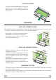
INSTALLAZIONE Foratura Piano di supporto e Montaggio Cappa MONTAGGIO CON VITI 220 • Il Piano di supporto della Cappa deve essere rientrante di 220 mm dal Piano inferiore dei Pensili. • Forare ø 4,5 mm il supporto utilizzando la Dima di foratura in dotazione. • Praticare un foro ø 150 mm sul Piano di supporto, utilizzando la Dima di foratura in dotazione. • Fissare con 4 Viti 12a (4,2 x 44,4) in dotazione.
PROFILO DI CHIUSURA • Lo spazio tra il bordo della Cappa e la Parete di fondo può essere chiuso applicando il Profilo 20 in dotazione con le Viti già predisposte a questo scopo. 20 Connessioni USCITA ARIA VERSIONE ASPIRANTE Per installazione in Versione Aspirante collegare la Cappa alla tubazione di uscita per mezzo di un tubo rigido o flessibile di ø150, la cui scelta è lasciata all’installatore. • Fissare il tubo con adeguate fascette stringitubo. Il materiale occorrente non è in dotazione.
USO Quadro comandi L M-V 3 2 1 0 0 1 L Luci Accende e spegne l’Impianto di Illuminazione. M Motore Accende e spegne il motore Aspirazione. V Velocità Determina le velocità di esercizio: 1. Velocità minima, adatta ad un ricambio d’aria continuo particolarmente silenzioso, in presenza di pochi vapori di cottura. 2. Velocità media, adatta alla maggior parte delle condizioni d’uso, dato l’ottimo rapporto tra portata d’aria trattata e livello sonoro. 3.
MANUTENZIONE Filtri antigrasso PULIZIA FILTRI ANTIGRASSO METALLICI • Necessitano di essere lavati almeno ogni 2 mesi circa di utilizzo o più frequentemente, per un uso particolarmente intenso. • Togliere i Filtri uno alla volta, agendo sugli appositi agganci. • Lavare i Filtri evitando di piegarli, e lasciarli asciugare prima di rimontarli. • Rimontarli facendo attenzione a mantenere la Maniglia verso la parte visibile esterna.
Dear Customer, If you follow the recommendations contained in this Instruction Manual, your appliance will give you constant high performance and will remain efficient for many years to come.
RECOMMENDATIONS AND SUGGESTIONS INSTALLATION • The manufacturer will not be held liable for any damages resulting from incorrect or improper installation. • The minimum safety distance between the cooker top and the extractor hood is 650 mm. • Check that the mains voltage corresponds to that indicated on the rating plate fixed to the inside of the hood. • For Class I appliances, check that the domestic power supply guarantees adequate earthing.
CHARACTERISTICS Dimensions 260 ø150 0 2 15 L Hood Type 60 90 L 598 898 28 0÷ Components Ref. 1 12a 1 20 GB 20 Q.ty Product Components 1 Hood Body, complete with: Controls, Light, Blower, Filters 1 Closing element Ref. 12a Q.ty Installation Components 4 Screws 4,2 x 44,4 Q.
INSTALLATION Drilling the Support surface and Fitting the Hood SCREW FITTING 220 • The hood support surface must be 220 mm above the bottom surface of the wall units. • Drill the support with a ø 4,5 mm drill bit, using the drilling template provided. • Cut a hole ø 150 mm in size on the support surface, using the drilling template provided. • Fix using the 4 screws 12a (4,2 x 44,4) provided. SNAP-ON FITTING • The hood can be installed either directly on the bottom surface of the wall units (min.
CLOSING ELEMENT • The space between the edge of the hood and the rear wall can be closed by applying the element 20 provided, using the screws supplied for this purpose. 20 Connections DUCTED VERSION AIR EXHAUST SYSTEM When installing the ducted version, connect the hood to the chimney using either a flexible or rigid pipe ø 150 mm, the choice of which is left to the installer. • Fix the pipe in position using sufficient pipe clamps (not supplied). • Remove any activated charcoal filters.
USE Control panel L 0 1 V L Light Switches the lighting system on and off. M Motor Switches the extractor motor on and off. V Speed Sets the operating speed of the extractor: 1. Low speed, used for a continuous and silent air change in the presence of light cooking vapour. 2. Medium speed, suitable for most operating conditions given the optimum treated air flow/noise level ratio. 3.
MAINTENANCE Grease filters CLEANING METAL GREASE FILTERS • The filters must be cleaned every 2 months of operation, or more frequently for particularly heavy usage. • Remove the filters, one at a time, after disconnecting the relative fastening elements. • Wash the filters, taking care not to bend them. Allow them to dry before refitting. • When refitting the filters, make sure that the handle is visible on the outside.
Chère Madame, Cher Monsieur, Si vous suivez attentivement les recommandations contenues dans ce mode d’emploi, votre hotte restera toujours efficace, et fournira constamment les mêmes performances.
CONSEILS ET SUGGESTIONS INSTALLATION • Le fabricant décline toute responsabilité en cas de dommage dû à une installation non correcte ou non conforme aux règles de l’art. • La distance minimale de sécurité entre le plan de cuisson et la hotte doit être de 650 mm au moins. • Vérifier que la tension du secteur correspond à la valeur qui figure sur la plaquette apposée à l’intérieur de la hotte.
CARACTERISTIQUES Encombrement 260 ø150 0 L Type de hotte L 60 90 598 898 0÷ 2 15 28 Composants Réf. 1 12a 1 20 Q.té Composants de Produit 1 Corps Hotte équipé de:Comandes, Lumière,Groupe Ventilateur,Filtres 1 Profil fermeture Réf. 12a Q.té Composants pour l ’installation 4 Vis 4,2 x 44,4 Q.
INSTALLATION Perçage du Plan de support et Montage de la Hotte MONTAGE AU MOYEN DE VIS 220 • Le Plan de support de la Hotte doit être monté plus en haut de 220 mm. par rapport au Plan inférieur des Armoires murales. • Percer un trou de ø 4,5 mm. sur le support, en utilisant le Gabarit de perçage fourni avec l’appareil. • Percer un trou de ø 150 mm. sur le Plan de support, en utilisant le Gabarit de perçage fourni avec l’appareil. • Fixer à l’aide des 4 Vis 12a (4,2 x 44,4) fournies avec l’appareil.
PROFIL DE FERMETURE • Il est possible de boucher l’espace entre le rebord de la Hotte et la Paroi du fond, en appliquant le Profil 20 fourni avec l’appareil, à l’aide des Vis déjà prévus à cet effet. 20 Branchements SORTIE AIR VERSION ASPIRANTE En cas d’installation en version aspirante, brancher la hotte à la tuyauterie de sortie via un tube rigide ou flexible de ø150, au choix de l’installateur. • Fixer le tube par des colliers appropriés. Le matériel nécessaire n’est pas fourni.
UTILISATION Tableau de commande L 0 1 V L Lumières Allume et éteint l’éclairage. M Moteur Allume et éteint le moteur aspiration V Vitesses Détermine les vitesses d’exploitation ainsi subdivisées: 1. Vitesse minimale, pour un rechange d’air permanent particulièrement silencieux en cas de faibles vapeurs de cuisson. 2. Vitesse moyenne pour la plupart des conditions d’utilisation, étant donné le rapport optimal entre débit d’air traité et niveau sonore. 3.
ENTRETIEN Filtres anti-graisse NETTOYAGE FILTRES ANTI-GRAISSE METALLIQUES • Ils nécessitent d’être nettoyés environ tous les 2 mois d’emploi ou plus fréquemment en cas d’emploi particulièrement intense. • Retirer les filtres l’un après l’autre, en intervenant sur les dispositifs d’accrochage spécialement prévus. • Laver les filtres en évitant de les plier et les laisser sécher avant de les remonter. • Remonter les filtres en veillant à ce que la poignée reste vers la partie visible externe.
Sehr geehrte Damen und Herren, bitte lesen Sie die Bedienungsanleitung aufmerksam durch, damit Sie alle Möglichkeiten und Vorteile Ihrer neuen Dunstabzugshaube voll nutzen können und über lange Zeit hin gute Leistungen erzielen.
EMPFEHLUNGEN UND HINWEISE MONTAGE • Der Hersteller haftet nicht für Schäden, die auf eine fehlerhafte und unsachgemäße Montage zurückzuführen sind. • Der minimale Sicherheitsabstand zwischen Kochmulde und Haube muss 650 mm betragen. • Prüfen, ob die Netzspannung mit dem Wert auf dem im Haubeninneren angebrachten Schild übereinstimmt. • Bei Geräten der Klasse I ist sicherzustellen, dass die elektrische Anlage des Wohnhauses über eine vorschriftsmäßige Erdung verfügt.
CHARAKTERISTIKEN Platzbedarf 260 ø150 0 L Hauben-typ 60 90 L 598 898 0÷ 2 15 28 Komponenten Pos. 1 St. 1 12a 20 1 1 Pos. St. Montagekomponenten 12a 4 Schrauben 4,2 x 44,4 St.
MONTAGE Bohren der Trägerplatte und Montage der Dunstabzugshaube MONTAGE MIT SCHRAUBEN 220 • Die Hauben-Trägerplatte muss 220 mm oberhalb der Oberschrank-Unterfläche positioniert werden. • Mit Hilfe des beiliegenden Bohrplanes Löcher ø 4,5 mm in die Trägerplatte bohren. • Mit Hilfe des beiliegenden Bohrplanes ein Loch ø 150 mm in die Trägerplatte bohren. • Mit 4 der mitgelieferten Schrauben 12a (4,2 x 44,4) fixieren.
ABDECKPROFIL • Der Bereich zwischen Haubenkante und Rückwand kann mit Hilfe des mitgelieferten Abdeckprofils 20 und der für diesen Zweck vorgesehenen Schrauben geschlossen werden. 20 Anschlüsse ANSCHLUSS IN ABLUFTVERSION Bei Abluftbetrieb kann die Haube vom Installateur wahlweise mittels Rohr oder Schlauch (ø 150 ) an die Außenrohrleitung angeschlossen werden. • Das Rohr mit geeigneten Rohrschellen fixieren. Das hierzu erforderliche Material wird nicht mitgeliefert.
BEDIENUNG Bedienfeld L 0 1 V L Beleucht Schaltet die Beleuchtung ein und aus. M Motor Schaltet den Gebläsemotor ein und aus. V Geschw. Steuert folgende Geschwindigkeitsstufen: 1. geringste Gebläsestufe, diese Stufe ist für einen ständigen und besonders leisen Luftaustausch bei geringer Kochdunstentwicklung geeignet; DE 2. mittlere Gebläsestufe, eignet sich aufgrund des guten Verhältnisses zwischen Fördervolumen und Geräuschentwicklung für die meisten Anwendungssituationen; 3.
WARTUNG Fettfilter SELBSTTRAGENDE METALLFETTFILTER - FILTERREINIGUNG • Sie müssen nach 2-monatigem Betrieb bzw. bei starkem Einsatz auch häufiger gereinigt werden. • Die Filter einzeln entnehmen, indem die entsprechenden Haltevorrichtungen gelöst werden. • Die Filter reinigen (darauf achten, sie nicht zu verbiegen) und vor der Remontage trocknen lassen. • Bei der Remontage ist darauf zu achten, dass sich der Griff auf der sichtbaren Außenseite befindet.
Geachte mevrouw, meneer, Als u de in deze Gebruiksaanwijzing beschreven aanbevelingen zorgvuldig opvolgt, blijft uw kap steeds in goede staat en zal hij altijd optimale prestaties leveren.
ADVIEZEN EN SUGGESTIES INSTALLATIE • De fabrikant aanvaardt geen enkele aansprakelijkheid voor schade die voortkomt uit onjuiste of niet overeenkomstig de regels der kunst uitgevoerde installaties. • De minimale veiligheidsafstand tussen de kookplaat en de wasemkap bedraagt 650 mm. • Controleer of de netspanning correspondeert met de spanning die aangegeven is op het plaatje aan de binnenkant van de wasemkap.
EIGENSCHAPPEN Buitenafmetingen 260 260 ø150 ø150 2 15 0÷ 52 1 0÷ L L Type Wasemkap L 60 90 598 898 0 28 0 28 Onderdelen 12a 1 Ref. 1 1 20 1 Productonderdelen Wasemkap compleet met:Bedieningen, Licht, Ventilatorgroep, Filters Sluitprofiel Ref.
INSTALLATIE Boren van gaten in draagvlak en montage kap MONTAGE MET SCHROEVEN 220 • Het draagvlak van de kap moet 220 mm hoger zijn dan het ondervlak van de hangkastjes. • Boor een gat van ø 4,5 mm in de drager met behulp van de bijgeleverde boormal. • Boor een gat van ø 150 mm in het draagvlak met behulp van de bijgeleverde boormal. • Bevestig met de 4 bijgeleverde schroeven 12a (4,2 x 44,4).
SLUITPROFIEL • De ruimte tussen de rand van de kap en de achterwand kan worden afgesloten met behulp van het bijgeleverde profiel 20 met de voor dit doel reeds aanwezige schroeven. 20 Aansluitingen LUCHTUITLAAT AFZUIGVERSIE Bij installatie in afzuigversie, moet u de wasemkap met de uitlaatleiding verbinden door middel van een starre of buigzame leiding van ø 150 mm, naar keuze van de installateur. • Zet de leiding vast met geschikte leidingklemmen.
GEBRUIK Bedieningspaneel L 0 1 V L Lichten Hiermee schakelt u de verlichting aan en uit M Motor Hiermee schakelt u de afzuigmotor aan en uit V Snelheid Instelling van de werkingssnelheid: 1. Minimumsnelheid, geschikt voor een continue en zeer stille luchtverversing, als er weinig kookdampen zijn. 2. Gemiddelde snelheid, geschikt voor de meeste gebruiksomstandigheden, gezien de uitstekende verhouding tussen de hoeveelheid behandelde lucht en het geluidsniveau. 3.
ONDERHOUD Vetfilters REINIGING VAN DE ZELFDRAGENDE METALEN VETFILTERS • De filters moeten eens in de 2 maanden of, bij bijzonder intensief gebruik, vaker gereinigd worden. • Verwijder de filters één voor één door de bevestigingen los te maken. • Was de filters en vermijd hierbij ze te buigen, en laat ze drogen alvorens ze terug te plaatsen. • Plaats de vetfilters terug en let er hierbij op dat de handgreep zichtbaar blijft.
Estimada señora, estimado señor, Si sigue con atención los consejos contenidos en este manual de instrucciones, su campana funcionará siempre de manera eficaz y podrá obtener siempre las mejores prestaciones.
CONSEJOS Y SUGERENCIAS INSTALACIÓN • El fabricante declina cualquier responsabilidad debida a los daños provocados por una instalación incorrecta o no conforme con las reglas. • La distancia mínima de seguridad entre la encimera y la campana debe ser de 650 mm. • Comprobar que la tensión de red corresponda a la indicada en la placa situada en el interior de la campana. • Para los aparatos de 1ª clase asegurarse de que la instalación eléctrica doméstica posea una toma de tierra eficaz.
CARACTERÍSTICAS Dimensiones 260 ø150 0 2 15 0÷ L Tipo Campana L 60 90 598 898 28 Componentes Ref. 1 12a 20 Cant. Componentes del producto 1 Cuerpo campana dotado con:mandos,luz, grupo de ventilación,filtros. 1 Perfil de cierre Ref. Cant. Componentes de instalación 12a 4 Tornillos 4,2 x 44,4 1 4 Cant.
INSTALACIÓN Taladrado de la superficie de soporte y montaje de la campana MONTAJE CON TORNILLOS 220 • La superficie de soporte de la campana debe encontrarse 220 mm por encima de la superficie inferior del mueble colgante. • Taladrar ø 4,5 mm el soporte utilizando la plantilla de perforación suministrada en dotación. • Hacer un orificio ø 155 mm en la superficie de soporte, usando la plantilla de perforación suministrada en dotación. • Fijar con los 4 tornillos 12a (4,2 x 44,4) en dotación.
PERFIL DE CIERRE • El espacio entre el borde de la campana y la pared de fondo se puede cerrar aplicando el perfil 20 en dotación con los tornillos ya predispuestos para este objeto. 20 Conexiones SALIDA DEL AIRE VERSIÓN FILTRANTE Para la instalación de la versión aspirante, conectar la campana al tubo de salida mediante un tubo rígido o flexible de 150 mm, a discreción del instalador. • Fijar el tubo con abrazaderas adecuadas. Este material no se proporciona en dotación.
USO Tablero de mandos L 0 1 V L Luces Enciende y apaga la instalación de iluminación. M Motor Enciende y apaga el motor de aspiración. V Velocidad Determina las velocidades de ejercicio. 1. Velocidad mínima, indicada para un recambio de aire continuo muy silencioso, en presencia de pocos vapores de cocción. 2. Velocidad media, indicada para la mayor parte de las condiciones de uso, gracias a la óptima relación entre caudal de aire tratado y nivel de ruido. 3.
MANTENIMIENTO Filtros antigrasa LIMPIEZA DE LOS FILTROS ANTIGRASA METÁLICOS Limpieza de los Filtros • Requieren un lavado cada 2 meses aproximadamente o más a menudo si su uso es muy intenso. • Quitar los filtros uno por vez, operando en los enganches correspondientes. • Lavar los filtros evitando que se doblen y dejarlos secar antes de volverlos a montar.. • Montar los filtros prestando atención en mantener la manija hacia la parte visible exterior.
Quest’apparecchio è conforme alla norma europea sulla bassa tensione C.E.E. 73/23 relativa alla sicurezza elettrica e alle norme europee: C.E.E. 89/336 relativa alla compatibilità elettromagnetica e C.E.E. 93/68 relativa alla marcatura CE. This appliance conforms to European Low Voltage Directive 73/23/CEE governing electrical safety, European Directive 89/336/CEE on Electromagnetic Compatibility and Directive 93/68/CEE regarding CE Marking.