Manuel d’Instructions Instructions Manual Manual de instrucciones Libretto Istruzioni KSEU912X
INDEX WARNINGS AND REQUIREMENTS .................................................................................................................................... 3 RECOMMENDATIONS AND SUGGESTIONS ..................................................................................................................... 6 DIMENSIONS and MAIN PARTS .......................................................................................................................................... 7 INSTALLATION .............
READ AND SAVE THESE INSTRUCTIONS The Installer must leave these instructions with the homeowner. The homeowner must keep these instructions for future reference and for local electrical inspectors’ use. READ THESE INSTRUCTIONS BEFORE YOU START INSTALLING THIS RANGEHOOD WARNING: - TO REDUCE THE RISK OF A RANGE TOP GREASE FIRE: Never leave surface units unattended at high settings. Boilovers cause smoking and greasy spillovers that may ignite. Heat oils slowly on low or medium setting.
WARNING • • • • • • Venting system MUST lead the air outside the building. DO NOT expel the air through a ductwork in an attic or other enclosed space. DO NOT use 4" laundry-type wall caps. Flexible-type ductwork is NOT recommended. DO NOT obstruct the flow of combustion and ventilation air. Failure to follow venting requirements may result in a fire. ELECTRICAL REQUIREMENTS A 120 volt, 60 Hz AC-only electrical supply is required on a separate 15 amp fused circuit.
WARNING - TO REDUCE THE RISK OF FIRE, ELECTRICAL SHOCK, OR INJURY TO PERSONS, OBSERVE THE FOLLOWING: Installation Work And Electrical Wiring Must Be Done By Qualified Person(s) In Accordance With All Applicable Codes And Standards, Including Fire-Rated Construction. Sufficient air is needed for proper combustion and exhausting of gases through the flue (chimney) of fuel burning equipment to prevent backdrafting.
RECOMMENDATIONS AND SUGGESTIONS The Instructions for Use apply to several versions of this appliance. Accordingly, you may find descriptions of individual features that do not apply to your specific appliance. INSTALLATION • The manufacturer will not be held liable for any damages resulting from incorrect or improper installation. • Check that the main voltage corresponds to that indicated on the rating plate fixed to the inside of the hood.
DIMENSIONS and MAIN PARTS 5" 1/8 12" 1/2 21" 1/4 3" 1/2 2" 7/16 10" 5/8 19" 5/16 2" 3/8 Min. 35" - Max.38" 1/8 Dimensions 12" 35" 3/8 Components Ref. 1 2 2.1 2.2 8a 8b 10 14.1 15 Q.ty Product Components 1 Hood Body, complete with: Controls, Light, Blower, Filters 1 Telescopic Chimney comprising: 1 Upper Section 1 Lower Section 1 Right Air Outlet Grill Aria 1 Left Air Outlet Grill Aria 1 Damper 2 Air Outlet Connection Extension 1 Air Outlet Connection 15 12a 7.2.1 EN 11 10 2.1 2 8b 2.
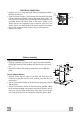
INSTALLATION Wall drilling and bracket fixing ÷1/16" 24" 12a 4"9/16 4"9/16 12"5/8 11 X 7.2.1 Wall marking: • Draw a vertical line on the supporting wall up to the ceiling, or as high as practical, at the center of the area in which the hood will be installed. • Draw a horizontal line at 24” above the hob. • Place bracket 7.2.1 on the wall as shown about 1/16” from the ceiling or upper limit aligning the center (notch) with the vertical reference line.
Mounting the hood body Vr • Before attaching the hood body, tighten the two screws Vr located on the hood body mounting points. • Hook the hood body onto the screws 12a. • Fully tighten support screws 12a. • Adjust screws Vr to level the hood body. 12a Note: The Hood body should be secured to wall studs. If necessary, install a wood support behind the dry wall, flush mounted between 2 studs. This will provide the necessary structure and support for mounting.
ELECTRICAL CONNECTION • Remove the cover from the Field Wiring Compartment with a phillips screwdriver. • Feed the Power Supply Cable through the electrical knockout. Connect the Power Supply Cable to the range- hood cable. Attach the Power Supply Cable grounding lead to the green screw provided. Attach the White lead of the power supply to the White lead of the rangehood with a twist-on type wire connector.
USE Control board Key A B C D E F G H I L Function Display Switches the motor on/off at the latest selected speed Decreases the suction speed. Increases the suction speed. By pressing this key it is possible to start the intensive speed from any previously selected speed. This speed has been timed at 6 minutes. After that time the system activates automatically the latest selected speed.
CARE Metal grease filters Filters can be washed in the dishwasher. They need to be washed when FG-sign appears on the display or in any case every 2 months, or even more frequently in case of particularly intensive use of the hood. Alarm reset • Press the G-key for at least 3 seconds (See Use Paragraph). Cleaning • Remove the filters one at a time, supporting them with one hand and turning the safety knobs (pull and turn). • Wash the filters. Pay attention not to bend them.
Charcoal filter (ductless version) This filter cannot be washed or regenerated. It has to be replaced when the FC appears on the display or at least once every 4 months. Activation of the alarm signal • In the recycling version hoods the filter saturation alarm has to be activated during the installation or later. • Switch off the hood and the lights.