Contents 1.1 1.2 1.3 1.4 1.5 1.6 1.7 General safety instructions Manufacturer liability Appliance purpose Disposal Identification plate This user manual How to read the user manual 2 Description 2.1 General Description 2.2 Symbols 3 Use 30 30 33 33 33 34 34 34 35 35 36 37 3.1 Instructions 3.2 First use 3.3 Using the hob 37 37 38 4 Cleaning and maintenance 40 4.1 Instructions 4.2 Cleaning the appliance 40 40 5 Installation 5.1 5.2 5.3 5.4 5.5 5.
Instructions 1 Instructions 1.1 General safety instructions Risk of personal injury • During use the appliance and its accessible parts become very hot. Never touch the heating elements during use. • Protect your hands by wearing oven gloves when moving food inside the oven. • Never try to put out a fire or flames with water: turn off the appliance and smother the flames with a fire blanket or other appropriate cover.
• Do not use aerosols in the vicinity of this appliance whilst it is in use. • Switch off the appliance after use. • Do not modify this appliance. • Do not try to repair the appliance yourself or without the intervention of a qualified technician. • Do not pull the cable to remove the plug. • If the power supply cable is damaged, contact technical support immediately and they will replace it. Risk of damaging the appliance • Do not sit on the appliance. • Do not use steam jets to clean the appliance.
Instructions Installation • This appliance must not be installed in a boat or caravan. • This appliance must not be installed on a pedestal. • Position the appliance into the cabinet cut-out with the help of a second person. • To prevent any possible overheating, the appliance should not be installed behind a decoration door or a panel. • Before any operation on the appliance (installation, maintenance, positioning or movement) always wear PPM.
Instructions The manufacturer declines all liability for damage to persons or property caused by: • use of the appliance other than the one envisaged, • failure to comply with the instructions in the user manual, • tampering with any part of the appliance, • use of non-original spare parts. 1.3 Appliance purpose • This appliance is intended for cooking food in the home environment. Every other use is considered inappropriate.
Instructions 1.5 Identification plate The identification plate bears the technical data, serial number and brand name of the appliance. Do not remove the identification plate for any reason. 1.6 This user manual This user manual is an integral part of the appliance and must therefore be kept in its entirety and within the user’s reach for the whole working life of the appliance. Read this user manual carefully before using the appliance. 1.
Description 2 Description EN 2.
Description 100 cm AUX = Auxiliary SR = Semi-rapid RR = Reduced rapid R = Rapid UR = Ultra rapid 2.2 Symbols Cooking zones Burner knobs Front left Centre left Rear left Central Rear right Central right Front right 36 Useful for lighting and adjusting the hob burners. Press and turn the knobs anticlockwise to the value to light the relative burners. Turn the knobs to the zone between the maximum and minimum setting to adjust the flame. Return the knobs to the position to turn off the burners.
Use 3 Use Improper use Danger of burns • Make sure that the flame-spreader crowns are correctly positioned in their seats with their respective burner caps. • Oils and fats could catch fire if overheated. Be very careful. • Do not leave the appliance unattended during cooking operations where fats or oils could be released. • Do not spray any spray products near the appliance. • Do not touch the appliance's heating elements when it is running. Leave them to cool before cleaning.
Use 3.3 Using the hob All the appliance’s control and monitoring devices are located together on the front panel. The burner controlled by each knob is shown next to the knob. The appliance is equipped with an electronic ignition device. Simply press the knob and turn it anticlockwise to the maximum flame symbol, until the burner ignites. If the burner does not light in the first 15 seconds, turn the knob to and wait 60 seconds before trying again.
1Practical tips for using the hob Using a griddle For better burner efficiency and to minimise gas consumption, use pans with lids and of suitable size for the burner, so that the flames do not reach up the sides of the pan. Once the contents come to the boil, turn down the flame far enough to ensure that the liquid does not boil over. A few precautions are necessary if you wish to use a griddle: • The griddle can be pre-heated with the burner on maximum power for no more than 10 minutes.
Cleaning and maintenance 4 Cleaning and maintenance 4.1 Instructions Improper use Risk of damage to surfaces • Do not use steam jets to clean the appliance. • Do not use cleaning products containing chlorine, ammonia or bleach on parts made of steel or that have metallic surface finishes (e.g. anodizing, nickelor chromium-plating). • If it comes into contact with aggressive detergents, hard water or spills (cooking water, sauces, coffee, etc.), clean immediately after having let the hob cool down.
Cleaning and maintenance For correct operation the igniters and thermocouples must always be perfectly clean. Check them frequently and clean them with a damp cloth if necessary. Remove any dry residues with a wooden toothpick or a needle. Refit the flame-spreader crowns making sure that they are correctly positioned in their housings with their respective burner caps.
Installation 5 Installation 5.2 Section cut from the countertop The following operation requires building and/or carpentry work and must therefore be carried out by a competent tradesman. Installation can be carried out on various materials such as masonry, metal, solid wood or plastic laminated wood as long as they are heat resistant (>90°C). 5.1 Safety instructions Heat production during appliance operation Risk of fire • Check that the carcase material is heat resistant.
5.3 Mounting Over empty kitchen unit or drawers Over built-in oven unit If there are other pieces of furniture (lateral walls, drawers, etc.), dishwashers or fridges under the hob, a double-layer wooden base must be installed at least 20 mm from the bottom of the hob to avoid any accidental contact. It must only be possible to remove the double-layer base using suitable equipment.
Installation Fixing brackets Screw the fixing brackets (A) into the holes on the sides of the bottom casing to properly fasten the hob to the structure. With steel hob To prevent leakage of liquid between the frame of the hob and the work surface, put the insulating seal provided in position before assembly. 1. Refer to the dimensions in the figure, bearing in mind that the long front side must brush against the hole. Do not use silicone to secure the hob.
Installation Gas leak Danger of explosion • After carrying out any operation, check that the tightening torque of gas connections is between 10 Nm and 15 Nm. • If required, use a pressure regulator that complies with current regulations. • At the end of the installation, check for any leaks with a soapy solution, never with a flame. • The hoses should not come into contact with moving parts and should not be crushed in any way.
Installation Connection with a steel hose with conical fitting Make the connection to the gas mains using a continuous wall steel hose whose specifications comply with the applicable standard. Carefully screw the hose connector 3 to the appliance’s gas connector 1 (½” thread ISO 228-1), placing the supplied seal 2 between them. Apply insulating material to the thread of connector 3, then tighten the steel hose 4 to the connector 3.
Installation The combustion products may be extracted by means of hoods connected to a natural draught chimney whose efficiency is certain or via forced extraction. An efficient extraction system requires precision planning by a specialist qualified in this area and must comply with the positions and clearances indicated by the applicable standards. When the job is complete, the installer must issue a certificate of conformity.
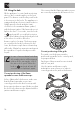
Installation Removing the hob top 1. Remove the grids from the hob. 2. Remove the flame-spreader crowns and relative burner caps. 3. Pull the knobs and the knob bezels upwards to remove them. Between knob and the knob bezel there is a spring that is not shown in the figure. 4. For each burner, unscrew the three screws that fix the burner support rings to the hob top.
Installation Replacing nozzles EN 5. Remove the screws that fasten the hob top to the burner casing (the figure shows the 60 cm model as an example). 6. Lift the hob top and remove it. 1. Unscrew screw A and push air regulator B as far as it will go. 2. Use a spanner to remove the nozzles C and install the new ones for the required gas supply, following the indications given in the relevant table (see “Gas types and Countries”). The nozzle tightening torque must be no more than 3 Nm. 3.
Installation Adjusting the minimum setting for natural or town gas 1. Light the burner and turn it to the minimum position. 2. Extract the gas cock knob and turn the adjustment screw next to the tap rod (depending on the model) until the correct minimum flame is achieved. 3. Refit the knob and verify that the burner flame is stable. 4. Turn the knob rapidly from the maximum to the minimum setting: The flame should not go out. 5. Repeat the operation on all gas cocks.
Installation N° Gas Types 1 Natural Gas G20 G20 20 mbar G20/25 20/25 mbar 2 Natural Gas G25 G25 20 mbar 3 Natural Gas G2.350 G2.
Installation Burner and nozzle characteristics tables 1 Natural Gas G20 AUX SR RR R UR Rated heating capacity (kW) 1.0 1.6 2.5 2.9 3.5 Nozzle diameter (1/100 mm) 67 87 106 115 122 Reduced flow rate (W) 400 500 900 900 1100 4 1 4 4 4 S1 AUX F4 SR M RR S R S UR Rated heating capacity (kW) 1.0 1.6 2.4 2.9 3.
6 LPG G30/31 Rated heating capacity (kW) AUX SR RR R UR 1.0 1.60 2.50 2.90 3.50 Nozzle diameter (1/100 mm) 46 58 72 76 85 Reduced flow rate (W) 450 550 950 950 1300 Primary air (mm) 10 10 10 10 10 - - - - - Rated flow rate G30 (g/h) 73 116 182 211 254 Rated flow rate G31 (g/h) 71 AUX 114 SR 179 RR 207 R 250 UR Marking on nozzle 7 Town Gas G110 Rated heating capacity (kW) 1.0 1.6 2.5 2.9 3.
Installation 5.6 Electrical connection Power voltage Danger of electrocution • Have the electrical connection performed by authorised technical personnel. • Use personal protective equipment. • The appliance must be connected to earth in compliance with electrical system safety standards. • Disconnect the mains power supply. • Do not pull the cable to remove the plug. • Use cables withstanding a temperature of at least 90°C. • The tightening torque of the screws of the terminal supply wires must be 1.