Contents 1.1 1.2 1.3 1.4 1.5 1.6 1.7 1.8 56 General safety instructions Manufacturer liability Appliance purpose Identification plate This user manual Disposal How to read the user manual To save energy 2 Description 2.1 2.2 2.3 2.4 2.5 64 General Description Cooking hob Control panel Other parts Available accessories 3 Use 3.1 3.2 3.3 3.4 3.5 3.6 Cleaning the hob Cleaning the door Cleaning the oven cavity Vapor Clean Extraordinary maintenance 5 Installation 5.1 5.2 5.3 5.4 5.
Instructions 1 Instructions 1.1 General safety instructions Risk of personal injury • During use the appliance and its accessible parts become very hot. Keep children well away from the appliance. • Protect your hands by wearing oven gloves when moving food inside the oven. • Never try to put out a fire or flames with water: turn off the appliance and smother the flames with a fire blanket or other appropriate cover.
• Keep the oven door closed during cooking. • If you need to move food or at the end of cooking, open the door 5 cm for a few seconds, let the steam come out, then open it fully. • Do not open the storage compartment (where present) when the oven is on and still hot. • The items inside the storage compartment could be very hot after using the oven. • Switch off the appliance after use. • Do not pull the cable to remove the plug.
Instructions • Do not sit on the appliance. • Racks and trays should be inserted as far as they will go into the side guides. The mechanical safety locks that prevent them from being removed must face downwards and towards the back of the oven. • Never leave the appliance unattended during cooking operations where fats or oils could overheat and take fire. Be very careful • Danger of fire: do not store items on the cooking surfaces. • Do not spray any spray products near the oven.
• Do not put empty pans or frying pans on switched on cooking zones. • Do not use rough or abrasive materials or sharp metal scrapers. • Do not use cleaning products containing chlorine, ammonia or bleach on parts made of steel or that have metallic surface finishes (e.g. anodizing, nickel- or chromium-plating). • Do not wash the removable components such as the hob grids, flame-spreader crowns and burner caps in a dishwasher. • Never use the oven door to lever the appliance into place when fitting.
Instructions • The adjustment conditions for this appliance are shown on the gas setting label. • Have the gas connection performed by authorised staff. • Installation using a hose must be carried out so that the length of the hose does not exceed 2 metres when fully extended for steel hoses and 1.5 metres for rubber hoses. • The hoses should not come into contact with moving parts and should not be crushed in any way. • If required, use a pressure regulator that complies with current regulations.
• use of non-original spare parts. 1.3 Appliance purpose • This appliance is intended for cooking food in the home environment. Every other use is considered inappropriate. • The appliance is not designed to operate with external timers or with remote-control systems. 1.4 Identification plate The identification plate bears the technical data, serial number and brand name of the appliance. Do not remove the identification plate for any reason. 1.
Instructions • Deliver the appliance to the appropriate recycling centre for electrical and electronic equipment waste, or return it to the retailer when purchasing an equivalent product, on a one for one basis. Our appliances are packaged in non-polluting and recyclable materials. • Deliver the packing materials to the appropriate recycling centre. Plastic packaging Danger of suffocation • Do not leave the packaging or any part of it unattended. • Do not let children play with the plastic bags. 1.
Instructions EN 1.8 To save energy • Only preheat the appliance if the recipe requires you to do so. • Unless otherwise indicated on the package, defrost frozen foods before placing them in the oven. • When cooking several types of food it is recommended to cook the foods one after the other to make the best use of the already hot oven. • Use dark metal moulds: They help to absorb the heat better. • Remove all trays and racks which are not required during cooking.
Description 2 Description 2.
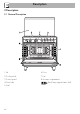
EN Description 1 Upstand 2 Cooking hob 3 Control panel 4 Oven light 5 Seal 6 Door 7 Fan 8 Storage compartment Rack/tray support frame shelf 2.
Description 2.3 Control panel 1 Programmer clock 4 Function knob For displaying the current time, setting programmed cooking operations and the minute minder timer. The oven’s various functions are suitable for different cooking modes. After selecting the required function, set the cooking temperature using the temperature knob. 2 Temperature knob This knob allows you to select the cooking temperature. Turn the knob clockwise to the required value, between the minimum and maximum setting.
Description 2.4 Other parts 2.5 Available accessories Shelves Tray rack (on some models only) EN The appliance features shelves to position trays and racks at different heights. The insertion heights are indicated from the bottom upwards (see 2.1 General Description). Interior lighting The appliance interior lighting comes on: • When the door is opened • When any function is selected, apart from the function. To be placed over the top of the oven tray; for cooking foods which may drip.
Description Rotisserie Ring reducers Useful when using small cookware. WOK ring Useful for cooking chicken and all foods which require uniform cooking over their entire surface. Rack Useful when using a wok. Some models are not provided with all accessories. The accessories intended to come into contact with food are made of materials that comply with the provisions of current legislation. Useful for supporting containers with food during cooking.
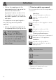
Use Instructions High temperature inside the oven during use Danger of burns • Keep the oven door closed during cooking. • Protect your hands wearing heat resistant gloves when moving food inside the oven. • Do not touch the heating elements inside the oven. • Do not pour water directly onto very hot trays. • Keep children under the age of 8 away from the appliance when it is in use.
Use High temperature inside the oven during use Danger of fire or explosion • Do not spray any spray products near the oven. • Do not use or leave flammable materials near the oven or the storage compartment. • Do not use plastic cookware or containers when cooking food. • Do not put sealed tins or containers in the oven. • Do not leave the oven unattended during cooking operations where fats or oils could be released. • Remove all trays and racks which are not required during cooking.
Use Tray rack (on some models only) The tray rack has to be inserted into the tray. In this way fat can be collected separately from the food which is being cooked. 3.1 Using the accessories Ring reducers The ring reducers have to be placed on the hob grids. Make sure they are placed properly. Racks and trays Racks and trays have to be inserted into the side guides until they come to a complete stop.
Use Rotisserie 1. Insert the 4 supplied bushings in the 4 corner holes of the deep tray and screw them onto the ring nuts with a suitable tool (such as a screwdriver). 2. Position the rotisserie supports in the bushings as shown in the figure below. 72 3. Prepare the rotisserie rod with the food using the clip forks provided. The clip forks can be tightened using the fastening screws. 4. Once you have prepared the rotisserie rod, place it on the supports.
5. Place the tray on the first runner (see “General Description”). 6. Insert the tip of the rod in the rotisserie motor housing on the left of the rear wall of the oven. 8. When cooking is complete, remove the tray with the rotisserie. 9. Screw on the handle provided so that you can handle the rotisserie rod more easily. 3.2 Using the hob These operations must be performed with the oven off and cold. 7.
Use The burner may go out when the knob is released: In this case, the thermocouple has not heated up sufficiently. Wait a few moments and repeat the operation. Keep the knob pressed in longer. In case of an accidental switching off, a safety device will be tripped, cutting off the gas supply, even if the gas cock is open. Return the knob to and wait at least 60 seconds before lighting it again.
3.4 Using the oven Switching on the oven To switch on the oven: 1. Select the cooking function using the function knob. 2. Select the temperature using the temperature knob. Ensure that the programmer clock shows the cooking duration symbol , otherwise it will not be possible to turn on the oven. Press the keys and at the same time to reset the programmer clock. Functions list Static As the heat comes from above and below at the same time, this system is particularly suitable for certain types of food.
Use Fan assisted The operation of the fan, combined with traditional cooking, ensures consistent cooking even with complex recipes. Perfect for biscuits and cakes, even when simultaneously cooked on several levels. (For multiple-level cooking, we recommend using the 2nd and 4th shelves.
Advice for cooking with the Grill and the Fan with grill • Meat can be grilled even when it is put into the cold oven or into the preheated oven if you wish to change the effect of the cooking. • With the Fan with grill function, we recommend that you preheat the oven before grilling. • We recommend placing the food at the centre of the rack. • With the Grill function, we recommend that you turn the temperature knob to the maximum value near the symbol to optimise cooking.
Use 3.6 Digital programmer Setting the time If the time is not set, the oven will not switch on. On the first use, or after a power failure, the digits will be flashing on the appliance’s display. 1. Press the keys and at the same time. The dot between the hours and the minutes flashes. Minute minder timer key Cooking duration key End of cooking key Decrease key Value increase key Ensure that the programmer clock shows the cooking duration symbol , otherwise it will not be possible to turn on the oven.
Use Timed cooking is the function which allows a cooking operation to be started and then ended after a specific length of time set by the user. 1. After selecting a cooking function and temperature, press the key . The display will show the digits and the symbol displayed between the hours and the minutes. 2. Use the key or to set the required minutes. 3. Wait approx. 5 seconds without pressing any key in order for the function to activate. The current time and the symbols and will appear on the display.
Use 3. Use the key or to set the required minutes. 4. Wait approx. 5 seconds without pressing any key in order for the function to activate. The current time and the Minute minder timer symbols and will appear on the display. 5. At the end of cooking the heating elements will be deactivated. On the The minute minder timer can be activated at any time. display, the symbol turns off, the symbol flashes and the buzzer sounds. 6. To turn off the buzzer just press any key of the programmer clock. 7.
Use Cooking information table Lasagne Pasta bake 3-4 3-4 Static Static Runner position from the bottom 1 1 Roast veal Pork loin Sausages Roast beef Roast rabbit Turkey breast Roast pork neck Roast chicken 2 2 1.5 1 1.5 3 2-3 1.
Cleaning and maintenance 4 Cleaning and maintenance Instructions Improper use Risk of damage to surfaces • Do not use steam jets to clean the appliance. • Do not use cleaning products containing chlorine, ammonia or bleach on parts made of steel or that have metallic surface finishes (e.g. anodizing, nickelor chromium-plating). • Do not use abrasive or corrosive detergents (e.g. scouring powders, stain removers and metallic sponges) on glass parts.
4.1 Cleaning the hob Igniters and thermocouples Cooking hob grids For correct operation the igniters and thermocouples must always be perfectly clean. Check them frequently and clean them with a damp cloth if necessary. Remove any dry residues with a wooden toothpick or a needle. Remove the grids and clean them in lukewarm water and non-abrasive detergent. Make sure to remove any encrustations. Dry them thoroughly and return them to the hob.
Cleaning and maintenance Cleaning the glass lid (on some models only) For easier cleaning, the lid can be taken off its hinges. 1. Lower the lid to closed position. 2. Unscrew the screws on the back of the hinges. 3. Open it and lift it upwards. 4. Clean. 5. Insert the lid into the guides. Tighten the fastening screws on the hinges in closed position. If liquids fall on the lid when it is closed, carefully remove them with a cloth before opening it. 4.2 Cleaning the door 2.
Cleaning and maintenance For easier cleaning the internal glass panes of the door can be removed. 1. Open the door. 2. Position the retaining clips in the holes in the hinges in order to prevent accidental closing of the door. 3. Pull the rear part of the internal glass pane gently upwards, following the movement indicated by the arrows (1). 5. Remove the intermediate glass pane by lifting it upwards. EN Removing the internal glass panes 6. Clean the external glass pane and the panes removed previously.
Cleaning and maintenance 4.3 Cleaning the oven cavity Removing the rack/tray support frames In order to keep your oven in the best possible condition, clean it regularly after letting it cool down. Avoid letting food residue dry inside the oven cavity, as this could damage the enamel. Take out all removable parts before cleaning. For easier cleaning, we recommend removing: • The door • The rack/tray support frames • The seal.
Cleaning and maintenance Vapor Clean is an assisted cleaning procedure which facilitates the removal of dirt. Thanks to this process, it is possible to clean the inside of the oven very easily. The dirt residues are softened by the heat and water vapour for easier removal at a later stage. • Pour approximately 40 cc of water into the tray. Make sure it does not overflow out of the cavity. EN 4.
Cleaning and maintenance 4.5 Extraordinary maintenance Vapor Clean setting 1. Turn the function knob to the symbol the temperature knob to the symbol and Installing and removing the seal . To remove the seal: • Unhook the clips in the 4 corners and in the centre, then pull the seal. 2. Set a cooking time of 18 minutes using the programmer clock. The Vapor Clean cycle starts a few seconds after the last press on the programmer clock keys. 3.
Cleaning and maintenance Replacing the internal light bulb 4. Slide out and remove the light bulb. EN Live parts Danger of electrocution • Unplug the appliance. The oven is fitted with a 40W light bulb. 1. Completely remove all accessories from inside the oven. 2. Remove the rack/tray support frames. 3. Remove the bulb cover using a tool (e.g. a screwdriver). Do not touch the halogen lamp directly with your fingers, but wrap it in an insulating material. 5. Fit the new light bulb. 6. Refit the cover.
Installation 5 Installation 5.1 Gas connection Gas leak Danger of explosion • After carrying out any operation, check that the tightening torque of gas connections is between 10 Nm and 15 Nm. • If required, use a pressure regulator that complies with current regulations. • At the end of the installation, check for any leaks with a soapy solution, never with a flame.
Installation Connection with a steel hose Make the connection to the gas mains using a continuous wall steel hose whose specifications comply with the applicable standard. Carefully screw the connector 3 to the gas connector 1 of the appliance, placing the seal 2 between them. Connection with a steel hose with bayonet fitting Connection using a rubber hose complying with current standards is only permitted if the hose can be inspected along its entire length.
Installation Connection to LPG Room ventilation Use a pressure regulator and make the connection on the gas cylinder following the guidelines set out in the standards in force. The appliance should be installed in rooms that have a permanent air supply in accordance with the standards in force. The room where the appliance is installed must have enough air flow for the regular combustion of gas and the necessary air change in the room itself.
Installation 5.2 Adaptation to different types of gas The appliance is preset for natural gas G20 at a pressure of 20 mbar. Improper installation Risk of malfunction • In the case of conversion to Town Gas G110 – 8 mbar (category 1a), do not use the burners provided, but request the special G110 burners kit from our Technical Assistance Service.
Installation 2. Replace the nozzles using a 7 mm socket wrench according to the gas to be used (see "Nozzle and burner specification tables"). Adjusting the minimum setting for LPG Tighten the screw located at the side of the cock rod clockwise all the way. Following adjustment to a gas other than the one originally set in the factory, replace the gas setting label on the appliance with the one corresponding to the new gas. The label is inserted inside the nozzle pack (where present).
Installation Gas types and Countries 1 Natural Gas G20 G20 20 mbar G20/25 20/25 mbar 2 Natural Gas G20 G20 25 mbar 3 Natural Gas G25 G25 25 mbar G25.3 25 mbar 4 Natural Gas G25.1 G25.1 25 mbar 5 Natural Gas G25 G25 20 mbar 6 Natural Gas G2.350 G2.
Installation Burner and nozzle characteristics tables 1 Natural Gas G20 Rated heating capacity (kW) Nozzle diameter (1/100 mm) Pre-chamber (printed on nozzle) Reduced flow rate (W) 2 Natural gas G20 Rated heating capacity (kW) Nozzle diameter (1/100 mm) Pre-chamber (printed on nozzle) Reduced flow rate (W) 3 Natural gas G25/G25.3 Rated heating capacity (kW) Nozzle diameter (1/100 mm) Pre-chamber (printed on nozzle) Reduced flow rate (W) 4 Natural gas G25.
7 LPG G30/31 Rated heating capacity (kW) Nozzle diameter (1/100 mm) Pre-chamber (printed on nozzle) Reduced flow rate (W) Rated flow rate G30 (g/h) Rated flow rate G31 (g/h) 8 LPG G30/G31 Rated heating capacity (kW) Nozzle diameter (1/100 mm) Pre-chamber (printed on nozzle) Reduced flow rate (W) Rated flow rate G30 (g/h) Rated flow rate G31 (g/h) 9 LPG G30/G31 Rated heating capacity (kW) Nozzle diameter (1/100 mm) Pre-chamber (printed on nozzle) Reduced flow rate (W) Rated flow rate G30 (g/h) Rated flow rat
Installation 5.3 Positioning Heavy appliance Crushing hazard • Position the appliance into the cabinet cut-out with the help of a second person. Pressure on the open door Risk of damage to the appliance • Never use the oven door to lever the appliance into place when fitting. • Avoid exerting too much pressure on the oven door when open. Any wall units installed above the appliance’s worktop must be positioned at least Y mm from it.
Installation EN Appliance overall dimensions B - Class 2 subclass 1 (Built-in appliance) A 900 mm B 600 mm C1 D min. 150 mm 900 - 915 mm H 750 mm I 450 mm L2 900 mm 1 Minimum distance from side walls or other flammable material. 2 Minimum cabinet width (=A). C - Class 2 subclass 1 (Built-in appliance) The appliance must be installed by a qualified technician and according to the regulations in force.
Installation Dimensions of the appliance: locations of gas and electric connections (mm) Positioning and levelling Heavy appliance Risk of damage to the appliance • Insert the front feet first and then the rear ones. • After making the gas and electrical connections, screw on the four feet supplied with the appliance. A 124 B 38 C 42 D 634 F min. 105 - max. 160 H 776 L 898 E = Electrical connection G = Gas connection 100 The appliance must sit level on the floor to ensure stability.
Installation Fastening to the wall 3. Assemble the fastening bracket. EN The anti-tip devices must be installed in order to prevent the appliance tipping over. 1. Screw the wall fastening plate to the rear of the appliance. 4. Align the base of the hook on the fastening bracket with the base of the slot on the wall fastening plate. 2. Adjust the height of the 4 feet.
Installation 5. Align the base of the fastening bracket with the ground and tighten the screws to fix the measurements. 6. Use 50 mm for the distance from the side of the appliance to the bracket holes. 102 7. Move the bracket onto the wall and mark the position of the holes to be drilled in the wall. 8. After drilling the holes in the wall, use wall plugs and screws to fasten the bracket to the wall. 9.
Installation Fitting the lid (on some models only) 3. Lower the lid onto the hob. EN 1. Install the two supports A and fasten them from below the hob using the corresponding screws B. 4. Fasten the lid to the hob using the screws C inserted in the rear of the two supports A. 2. Install the lid from above, parallel with the two supports A.
Installation Assembling the upstand (on some models only) The upstand provided is an integral part of the product. It must be fastened to the appliance prior to installation. The upstand must always be positioned and secured correctly on the appliance. 1. Unscrew the 2 nuts B on the back of the worktop. 2. Position the upstand above the worktop, taking care to align the pins C with the holes D. 3. Secure the upstand to the worktop by tightening the screws A. 5.
Installation 3 x 1.5 mm² three-core cable. The values indicated above refer to the cross-section of the internal conductor. The aforementioned power cables are sized taking into account the coincidence factor (in compliance with standard EN 60335-2-6). Fixed connection Fit the power line with an all-pole disconnection switch, with a clearance between its contacts that allows the complete disconnection as per the overvoltage category III, in compliance with the installation regulations.