
Instruction manual


Installation
96
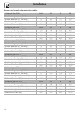
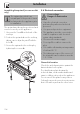
Burner and nozzle characteristics tables
1 Natural Gas G20 AUX SR R UR
Rated heating capacity (kW)
1.0 1.8 2.9 4.0
Nozzle diameter (1/100 mm)
72 94 115 145
Pre-chamber (printed on nozzle)
(X) (Y) (Y) (Z)
Reduced flow rate (W)
400 500 800 1600
2 Natural gas G20 AUX SR R UR
Rated heating capacity (kW)
1.0 1.8 2.9 4.0
Nozzle diameter (1/100 mm)
72 94 113 135
Pre-chamber (printed on nozzle)
(X) (Z) (H8) (S)
Reduced flow rate (W)
400 500 800 1600
3 Natural gas G25/G25.3 AUX SR R UR
Rated heating capacity (kW)
1.0 1.8 2.8 4.0
Nozzle diameter (1/100 mm)
72 94 115 148
Pre-chamber (printed on nozzle)
(X) (Y) (Y) (F3)
Reduced flow rate (W)
400 500 800 1600
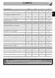
4 Natural gas G25.1 AUX SR R UR
Rated heating capacity (kW)
1.0 1.8 2.9 4.0
Nozzle diameter (1/100 mm)
77 100 134 152
Pre-chamber (printed on nozzle)
(F1) (Y) (F3) (F3)
Reduced flow rate (W)
400 500 800 1600
5 Natural gas G25 AUX SR R UR
Rated heating capacity (kW)
1.0 1.8 2.9 3.9
Nozzle diameter (1/100 mm)
77 100 134 152
Pre-chamber (printed on nozzle)
(F1) (Y) (F3) (F3)
Reduced flow rate (W)
400 500 800 1600
6 Natural gas G2.350 AUX SR R UR
Rated heating capacity (kW)
1.0 1.8 2.9 4.0
Nozzle diameter (1/100 mm)
94 120 165 210
Pre-chamber (printed on nozzle)
(Y) (Y) (F3) (H3)
Reduced flow rate (W)
400 500 800 1600