
Technical data
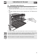
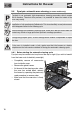
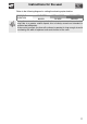

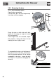
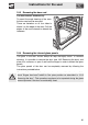

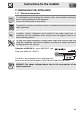
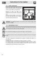
Table Of Contents
- 1. INSTRUCTIONS FOR USE
- 2. SAFETY PRECAUTIONS
- 3. ENVIRONMENTAL RESPONSIBILITY
- 4. GET TO KNOW YOUR OVEN
- 5. AVAILABLE ACCESSORIES
- 6. FRONT PANEL
- 7. USING THE OVEN
- 7.2.1 Internal oven lights
- 7.2.2 Oven runners
- 7.2.3 Cooling system
- 7.6.1 Cooking with a preset temperature
- 7.6.2 Changing the preset temperature
- 7.7.1 Cooking timed with the timer
- 7.7.2 Semi-automatic cooking
- 7.7.3 Automatic cooking
- 7.7.4 Changing the preset temperature
- 1 P1: OFF / ON Activate or deactivate the child safety lock (); this function, after 2 minutes of operation without any actions by the user, locks all the functions and knobs; it is identified by the appearance of on DSP1. To temporarily deactivate l...
- 2 P2: OFF / ON Activate or deactivate the Show Room function; this function disables all the heating elements so that only the control panel works (to use the oven normally, set P2:OFF).
- 3 P3: OFF / ON Activate or deactivate the function that allows a maximum consumption of 2300 W.
- 7.8.1 Change the settings in the secondary menu
- 8. COOKING WITH THE OVEN
- 9. CLEANING AND MAINTENANCE
- 10. EXTRAORDINARY MAINTENANCE
- 11. INSTALLING THE APPLIANCE
Instructions for the installer
84
11.2 Cable replacement
Should the supply cable need replacing,
remove the back guard by unscrewing the
screws to gain access to the terminal.
Replace the cable. The cable cross-
section must be no less than 1.5 mm² (3 x
1.5).
Make sure that the cables (for the oven or
any hob) follow the best route in order to
avoid any contact with the oven.
WARNING: The tightening torque of the screws of the terminal supply wires
must be 1.5 - 2 Nm.
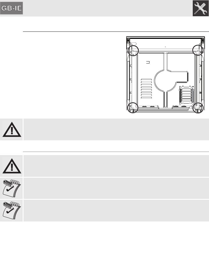
11.3 Positioning the oven
Never use the oven door to lever the oven into place when fitting. Avoid exerting
too much pressure on the oven door when open.
We recommend installing the oven with the help of a second person.
The base on which the oven is resting must be complete as shown in the figures
below.
The oven is designed for mounting into any piece of furniture as long as it is
heat-resistant.
Proceed according to the dimensions shown in Figures 1, 2 and 3.
For installing under a work top, follow the dimensions given in Figures 1 and 2.
For installing under a work top with combined cooking hobs, ensure a minimum
clearance from any side walls of at least 110 mm.