Instructions Manual STH600X - STH900X
INDEX EN RECOMMENDATIONS AND SUGGESTIONS ..................................................................................................................... 3 CHARACTERISTICS ............................................................................................................................................................. 4 INSTALLATION.................................................................................................................................................................
RECOMMENDATIONS AND SUGGESTIONS The Instructions for Use apply to several versions of this appliance. Accordingly, you may find descriptions of individual features that do not apply to your specific appliance. INSTALLATION • The manufacturer will not be held liable for any damages resulting from incorrect or improper installation.
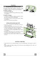
CHARACTERISTICS Dimensions Min. Min. 500mm 650mm Components Ref. 1 8 9 10 20 Q.ty Product Components 1 Hood Body, complete with: Controls, Light, Blower, Filters 1 Directional Air Outlet grille 1 Reducer Flange ø 150-120 mm 1 Damper ø 150 1 Closing element Ref. 12a 12b 12e Q.ty 4 2 2 Installation Components Screws 4,2 x 44,4 Screws 4,2 x 12,7 Screws 2,9 x 9,5 Q.
INSTALLATION Drilling the Support surface and Fitting the Hood SCREW FITTING • The hood support surface must be 135 mm above the bottom surface of the wall units. • Drill the support with a ø 4,5 mm drill bit, using the drilling template provided. • Cut a hole ø 150 mm in size on the support surface, using the drilling template provided. • Fix using the 4 screws 12a (4,2 x 44,4) provided.
Connections DUCTED VERSION AIR EXHAUST SYSTEM When installing the ducted version, connect the hood to the chimney using either a flexible or rigid pipe ø 150 or 120mm, the choice of which is left to the installer. To install a ø 150 pipe • To install the dumper 10 • Fix the pipe in position using sufficient pipe clamps (not supplied). To install a ø 120 pipe • To install a ø 120 mm air exhaust connection, insert the reducer flange 9 on the dumper 10.
USE Control panel L M-V 0 1 3 2 1 0 M-V L L Light M Motor V Speed EN Switches the lighting system L on and off. Switches the extractor motor M on and off. Sets the operating speed of V the extractor: 1. Low speed, used for a continuous and silent air change in the presence of light cooking vapour. 2. Medium speed, suitable for most operating conditions given the optimum treated air flow/noise level ratio. 3.
MAINTENANCE Grease filters CLEANING METAL CASSETTE GREASE FILTERS • The filters must be cleaned every 2 months, or more frequently in case of particularly heavy use of the hood. Filters can be washed in a dishwasher. • Pull out the sliding suction panel. • Remove the filters one by one, after having disconnected the relative fastening elements. • Wash the filters, taking care not to bend them. Let them get dry before refitting them.
991.0319.