Contents 1.1 1.2 1.3 1.4 1.5 1.6 1.7 General safety instructions Manufacturer’s liability Appliance purpose Identification plate This user manual Disposal How to read the user manual 2 Description 2.1 2.2 2.3 2.4 2.5 General Description Hob Control panel Other parts Available accessories 3 Use 3.1 3.2 3.3 3.4 3.5 3.6 4 8 8 8 8 8 9 10 10 11 12 13 13 15 To save energy Using the accessories Using the hob Using the storage compartment Using the ovens Programmer clock 4 Cleaning and maintenance 4.1 4.
Instructions 1 Instructions 1.1 General safety instructions Risk of personal injury • During use the appliance and its accessible parts become very hot. Never touch the heating elements during use. • Protect your hands by wearing oven gloves when moving food inside the oven. • Never try to put out a fire or flames with water: Turn off the appliance and smother the flames with a fire blanket or other appropriate cover.
• Do not open the storage compartment (where present) when the oven is on and still hot. • The items inside the storage compartment could be very hot after using the oven. • DO NOT USE OR STORE FLAMMABLE MATERIALS IN THE STORAGE COMPARTMENT (IF PRESENT) OR NEAR THE APPLIANCE. • DO NOT USE AEROSOLS IN THE VICINITY OF THIS APPLIANCE WHILST IT IS IN USE. • Switch off the appliance immediately after use. • DO NOT MODIFY THIS APPLIANCE.
Instructions • DO NOT FOR ANY REASON USE THE APPLIANCE AS A SPACE HEATER. • Do not spray any spray products near the oven. • Do not use plastic cookware or containers when cooking food. • Do not put sealed tins or containers in the oven. • Remove all trays and racks which are not required during cooking. • Do not cover the bottom of the oven cavity with aluminium or tin foil sheets. • Do not place pans or trays directly on the bottom of the oven cavity.
• Do not use abrasive or corrosive detergents (e.g. scouring powders, stain removers and metallic sponges) on glass parts. • Do not wash removable parts such as the hob pan support grids, flame-spreader crowns and burner caps in the dishwasher. • Never use the oven door to lever the appliance into place when fitting. • Avoid exerting too much pressure on the oven door when open. • Do not use the handle to lift or move the appliance. Installation • THIS APPLIANCE MUST NOT BE INSTALLED IN BOATS OR CARAVANS.
Instructions 1.2 Manufacturer’s liability The manufacturer declines all liability for damage to persons or property caused by: • Use of the appliance other than that specified • Failure to comply with the instructions in the user manual • Tampering with any part of the appliance • The use of non-original spare parts. 1.3 Appliance purpose • This appliance is intended for cooking food in the home environment. Every other use is considered improper.
• Deliver the appliance to the appropriate recycling centre for electrical and electronic equipment waste, or return it to the retailer when purchasing an equivalent product, on a one for one basis. Our appliances are packaged in non-polluting and recyclable materials. • Deliver the packing materials to the appropriate recycling centre. Plastic packaging Danger of suffocation • Do not leave the packaging or any part of it unattended. • Do not let children play with the plastic bags. 1.
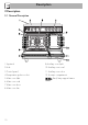
Description 2 Description 2.
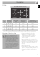
Description EN 2.2 Hob Zone Dimensions H x L (mm) Min. pan Ø (mm) Max. power draw (W)* Power draw in Booster function (W)* 1 190 x 196 120 2100 2300 2 190 x 196 120 1600 1850 3 270 x 270 145 2300 3000 4 180 x 180 110 1300 1400 5 210 x 210 120 2300 3000 * Power levels are approximate and can vary according to the pan used or the settings made. Advantages of induction cooking The hob is equipped with an induction generator for each cooking zone.
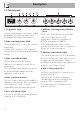
Description 2.3 Control panel 1 Programmer clock Useful for displaying the current time, setting programmed cooking operations and programming the minute minder timer. 2 Main oven temperature knob This knob allows you to select the cooking temperature. Turn the knob clockwise to the required value, between the minimum and maximum setting. 3 Main oven indicator light When flashing, it indicates that the appliance is heating up to reach the set temperature.
2.4 Other parts Shelves Interior lighting The appliance features shelves to position trays and racks at different heights. The insertion heights are indicated from the bottom upwards (see 2.1 General Description). The appliance’s interior lighting comes on: (main oven) • When any function is selected, apart from the function. When the door is open, it is not possible to turn off the interior lighting. 2.
Description Deep tray Tray rack Useful for collecting fat from foods placed on the rack above and for cooking pies, pizzas and baked desserts. To be placed over the top of the tray; for cooking foods which may drip. Some models are not provided with all accessories. The oven accessories intended to come into contact with food are made of materials that comply with the provisions of current legislation. Original supplied and optional accessories can be requested to Authorised Assistance Centres.
Use Instructions High temperature inside the oven during use Danger of burns • Keep the oven door closed during cooking. • Protect your hands by wearing oven gloves when moving food inside the oven. • Do not touch the heating elements inside the oven. • Do not pour water directly onto very hot trays. • Keep children under the age of 8 away from the appliance when it is in use.
Use High temperature inside the oven during use Danger of fire or explosion • Do not spray any spray products near the appliance. • Do not use or leave flammable materials near the oven or the storage compartment. • Do not use plastic cookware or containers when cooking food. • Do not put sealed tins or containers in the oven. • Do not leave the appliance unattended during cooking operations where fats or oils could be released. • Remove all trays and racks which are not required during cooking.
• Stop cooking a few minutes before the time normally used. Cooking will continue for the remaining minutes with the heat which has accumulated inside the oven. • Reduce any opening of the door to a minimum to avoid heat dispersal. • Keep the inside of the oven clean at all times. Racks and trays Racks and trays have to be inserted into the side guides until they come to a complete stop.
Use 3.3 Using the hob On first connection to the electrical mains, an automatic check will be carried out that will switch on all indicator lights for a few seconds. After use, turn off the hot plates used by returning the appropriate knob to the O position. Never rely solely on the cookware detector. To see whether the pan is suitable, bring a magnet close to the bottom: if it is attracted, the pan is suitable for induction cooking.
Cookware recognition Limiting the cooking duration When there is no saucepan on a cooking zone or if the saucepan is too small, no energy will be transmitted and the symbol will appear on the display. If there is a suitable saucepan on the cooking zone, the recognition system detects it and switches on the hob to the power level set using the knob. Energy transmission is also interrupted when the saucepan is removed from the cooking zone (the symbol will be shown on the display).
Use Advice on energy-saving Power levels • The diameter of the base of the pan must correspond to the diameter of the cooking zone. The power in the cooking zone can be adjusted to various levels. The table shows the levels suitable for various types of cooking. • When buying a pan, check whether the diameter indicated is that of the base or the top of the pan, as the top is almost always larger than the base.
Heating accelerator Each cooking zone is equipped with a heating accelerator that allows the maximum power to be delivered for a time that is proportional to the selected power. This function allows the selected power to be achieved in the shortest amount of time. 1. Turn the knob anticlockwise to position A and then release it. The display shows the symbol. 2. Select the required heating power (1 8) within 3 seconds. The selected power and the symbol will flash alternately on the display.
Use 2. Turn the front left cooking zone knob back to the 0 position and turn the rear left cooking zone knob until it reaches position 9. A prolonged beep will be emitted. Booster function The booster function allows the cooking zone to be activated at maximum power for as long as 5 minutes. It can be used to bring a large quantity of water to a boil rapidly or to broil meat. • Turn the knob clockwise to the P position for two seconds and then release. 3.
The flashing of a power level indicates that it will be automatically limited to a new level selected by the power control module. After a prolonged period of interruption to the power supply, the control lock will be deactivated. If this is the case, turn it back on as described above. Error codes If the display shows one of the following error codes , , contact Technical Assistance. Priority is given to the last zone set.
Use Hob power limitation The induction hob is configured to operate at 11.1 kW, but it can be set to operate at 7.4 kW, 4.8 kW or 3.7 kW. 1. Disconnect the appliance from the mains power supply and wait 10 seconds before turning the power back on. The power level of the hob must be set within 2 minutes of it being connected to the mains power supply. 2.
3.4 Using the storage compartment The storage compartment is at the bottom of the cooker. To open it, pull the handle towards you. It can be used to store cookware or metallic objects necessary when using the appliance. 3.5 Using the ovens Switching on the main oven 1. Select the cooking function using the function knob. 2. Select the temperature using the temperature knob. Ensure that the programmer clock shows the cooking duration symbol , otherwise it will not be possible to turn on the oven.
Use Grill The heat coming from the grill element gives perfect grilling results above all for thin and medium thickness meat and, in combination with the rotisserie (where fitted), gives the food an even browning at the end of cooking. Perfect for sausages, spare ribs and bacon. This function enables large quantities of food, particularly meat, to be grilled evenly. Fan + lower element The combination of the fan with just the lower heating element allows cooking to be completed more rapidly.
Switching on the auxiliary oven Turn the temperature/function knob to the required temperature, between 50°C and 245°C, or to the required function (at the maximum temperature). Auxiliary oven functions Oven light Turns on the oven light Grill The heat coming from the grill element gives perfect grilling results above all for thin and medium thickness meat and allows you to give the food an even browning at the end of the cooking. Perfect for sausages, spare ribs and bacon.
Use • With the Fan with grill function, we recommend that you preheat the oven before grilling. • We recommend placing the food at the centre of the rack. • For best results when using the Grill function, we recommend that you set it to the maximum temperature. Advice for cooking desserts/pastries and biscuits • Use dark metal moulds: They help to absorb the heat better. • The temperature and the cooking time depend on the quality and consistency of the dough.
The programmer clock only controls the main oven and does not control the auxiliary oven. Timed cooking Timed cooking is the function which allows a cooking operation to be started and then ended after a specific length of time set by the user. Setting the time If the time is not set, the oven will not switch on. On the first use, or after a power failure, the digits will be flashing on the appliance’s display. 1. Hold down the clock button for two seconds.
Use 7. Press the clock button programmer clock. to reset the It is not possible to set a cooking time of more than 10 hours. To cancel the set programming press and hold down the value increase and the value decrease buttons at the same time and then turn the oven off manually. Programmed cooking is the function which allows a cooking operation to be started at a set time and then ended after a specific length of time set by the user. 1.
10. Return the function and temperature knobs to 0. 11. To turn off the buzzer just press any button of the programmer clock. 12. Press the and buttons at the same time to reset the set program. It is not possible to set a cooking time of more than 10 hours. It is not possible to set a programmed cooking time of more than 24 hours. Minute minder timer The minute minder timer does not stop the cooking operation but rather informs the user when the set time has run out.
Use Modifying the set data 1. Press the clock button 3. Then switch off the oven manually if cooking is in progress. . 2. Use the value increase and value decrease buttons to set the number of minutes required. The buzzer can have 3 tones. 1. Hold down the value increase value decrease time. Deleting the set data 1. Press the clock button . and buttons at the same and buttons at the same 2. Press the clock button 2. Hold down the value increase value decrease time. Selecting the buzzer .
Use EN Main oven cooking information table Weight (Kg) Function Shelf Temperature (°C) Time (minutes) Lasagne Pasta bake 3-4 3-4 Static Static 1 1 220 - 230 220 - 230 45 - 50 45 - 50 Veal roast Pork loin Sausages Roast beef Roast rabbit Turkey breast Roast pork neck Roast chicken 2 2 1.5 1 1.5 3 2-3 1.
Cleaning and maintenance 4 Cleaning and maintenance Cleaning the surfaces Instructions To keep the surfaces in good condition, they should be cleaned regularly after use. Let them cool first. Improper use Risk of damage to surfaces • Do not use steam jets to clean the appliance. • Do not use cleaning products containing chlorine, ammonia or bleach on parts made of steel or that have metallic surface finishes (e.g. anodizing, nickelor chromium-plating). • Do not use abrasive or corrosive detergents (e.g.
4.1 Cleaning the hob Weekly cleaning Cleaning the glass ceramic hob Clean and maintain the hob once a week using an ordinary glass ceramic cleaning product. Always follow the manufacturer’s instructions. The silicon in these products creates a protective, water-repellent membrane which also resists dirt. All marks stay on the membrane and can therefore be removed easily. After cleaning, dry the surface with a clean cloth.
Cleaning and maintenance 4.2 Cleaning the door Removing the door For easier cleaning it is recommended to remove the door and place it on a tea towel. To remove the door proceed as follows: 1. Open the door completely and insert two pins into the holes on the hinges indicated in the figure. 3. To reassemble the door, put the hinges in the relevant slots in the oven, making sure that grooved sections A are resting completely in the slots.
Removing the internal glass panes For easier cleaning the internal glass panes of the door can be removed. 1. Remove the internal glass pane by pulling the rear part gently upwards, following the movement indicated by the arrows (1). This way, the 4 pins attached to the glass detach from their housings in the oven door. 2. Then, pull the front part upwards (2). 3.
Cleaning and maintenance 4.3 Cleaning the oven cavities Removing rack/tray support frames To keep the oven cavities in good condition, they should be cleaned regularly after having allowed them to cool. Avoid letting food residues dry inside the oven cavities, as this could damage the enamel. Take out all removable parts. Removing the guide frames enables the sides to be cleaned more easily. This operation should be performed each time the automatic cleaning cycle is used (on some models only).
4.4 Pyrolytic cycle Pyrolytic cleaning is an automatic, high-temperature cleaning procedure that causes dirt to dissolve. Thanks to this process, it is possible to clean the inside of the oven very easily. The Pyrolytic function is only for the main oven. Improper use Risk of damage to surfaces • Remove any food residues or large spills from previous cooking operations from the inside of the oven.
Cleaning and maintenance Setting of programmed pyrolytic cycle It is possible to program the pyrolytic cycle start time like all other cooking functions. 1. After having started the pyrolysis cycle (see “Setting up the pyrolytic function”), press and hold the button for 2 seconds. Be careful not to turn the function knob when setting the pyrolytic cycle. If you do, the settings entered via the programmer clock will be deleted and you will have to reset them. 2.
Cleaning and maintenance Installing and removing the seal To remove the seal: • Unhook the clips located in the 4 corners and in the centre, then pull the seal outwards. Replacing the internal light bulb EN 4.5 Extraordinary maintenance Live parts Danger of electrocution • Unplug the appliance. The oven is fitted with a 40 W light bulb. 1. Completely remove all accessories from inside the oven. 2. Remove the rack/tray support frames. 3. Remove the bulb cover using a tool (e.g. a screwdriver).
Cleaning and maintenance 4. Slide out and remove the light bulb. Do not touch the halogen light bulb directly with your fingers, but wrap it in insulating material. 5. Fit the new light bulb. 6. Refit the cover. Ensure the moulded part of the glass (A) is facing the door. 7. Press the cover completely down so that it attaches perfectly to the bulb support.
5 Installation 5.1 Positioning Heavy appliance Crushing hazard • Position the appliance into the cabinet cut-out with the help of a second person. Pressure on the open door Risk of damage to the appliance Any wall units installed above the appliance’s worktop must be positioned at least Y mm from it. If a hood is installed above the hob, refer to the hood instruction manual to ensure the correct clearance is left.
Installation Appliance overall dimensions B - Class 2 subclass 1 (Built-in appliance) A 900 mm B 600 mm C1 D min. 150 mm 900 - 915 mm H 750 mm I 450 mm L2 900 mm 1 Minimum distance from side walls or other flammable material. 2 Minimum cabinet width (=A). C - Class 2 subclass 1 (Built-in appliance) The appliance must be installed by a qualified technician and according to the regulations in force.
Appliance dimensions: location of electrical connection (mm) Positioning and levelling Heavy appliance Risk of damage to the appliance • Insert the front legs first and then the rear ones. • After making the gas and electrical connections, screw on the four legs supplied with the appliance. A 124 B 38 F min. 70 - max. 110 H 809 L 898 E = Electrical connection The appliance must sit level on the floor to ensure stability.
Installation Fastening to the wall 3. Assemble the fastening bracket. The anti-tip devices must be installed in order to prevent the appliance from tipping over. 1. Screw the wall fastening plate to the rear of the appliance. 4. Align the base of the hook on the fastening bracket with the base of the slot on the wall fastening plate. 2. Adjust the height of the 4 legs.
Installation 6. Use 50 mm for the distance from the side of the appliance to the bracket holes. 7. Move the bracket onto the wall and mark the position of the holes to be drilled in the wall. EN 5. Align the base of the fastening bracket with the ground and tighten the screws to fix the measurements. 8. After drilling the holes in the wall, use wall plugs and screws to fasten the bracket to the wall. 9.
Installation Assembling the upstand The upstand provided is an integral part of the product. It must be fastened to the appliance prior to installation. The upstand must always be positioned and secured correctly on the appliance. 1. Loosen the 4 screws (A) on the back of the hob (2 for each side) using a screwdriver. 2. Place the upstand on the hob. 3. Align the slots of the upstand (B) with the screws (A). 5.
The appliance can work in the following modes: • 220-240 V 2~ The aforementioned power cables are sized taking into account the coincidence factor (in compliance with standard EN 60335-2-6). Replacement clamp 3 x 10 mm² three-core cable. • 220-240 V 3~ 4 x 6 mm² four-core cable. • 220-240 V 1N~ In the event of connection to a two- or three-phase supply, the installed clamp must be replaced with the one supplied in order to ensure correct fastening of the cable.
Installation Accessing the terminal board To connect the power supply cable, you must access the terminal board on the rear casing: 1. Remove the screws fastening the plate to the rear casing. It is recommended to slacken off the cable clamp screw before installing the power supply cable. 4. When finished, replace the plate on the rear casing and secure it in place using the screws that were previously removed. 2. Gently rotate the plate and remove it from its seat. 5.3 Instructions for the installer 3.