Table of contents 1.1 1.2 1.3 1.4 1.5 1.6 1.7 General safety instructions Manufacturer liability Appliance purpose Identification plate This user manual Disposal How to read the user manual 2 Description 2.1 2.2 2.3 2.4 2.5 General Description Cooking hob Control panel Other parts Available accessories 3 Use 3.1 3.2 3.3 3.4 3.5 3.6 Cleaning the hob Cleaning the doors Cleaning the oven cavities Vapor Clean (multifunction oven only) Extraordinary maintenance 5 Installation 5.1 5.2 5.3 5.4 5.
Instructions 1 Instructions 1.1 General safety instructions Risk of personal injury • During use the appliance and its accessible parts become very hot. Never touch the heating elements during use. • Protect your hands by wearing oven gloves when moving food inside the oven. • Never try to put out a fire or flames with water: turn off the appliance and smother the flames with a fire blanket or other appropriate cover.
• While cooking do not place metal objects, such as cutlery or dishes on the hob surface as they may overheat. • Do not insert pointed metal objects (cutlery or utensils) into the slots in the appliance. • Do not pour water directly on very hot trays. • Keep the oven door closed during cooking. • If you need to move food or at the end of cooking, open the door 5 cm for a few seconds, let the steam come out, then open it fully.
Instructions Risk of damaging the appliance • Do not use abrasive or corrosive detergents (e.g. scouring powders, stain removers and metallic sponges) on glass parts. • Use wooden or plastic utensils. • Racks and trays should be inserted as far as they will go into the side guides. The mechanical safety locks that prevent them from being removed must face downwards and towards the back of the oven cavity. • Do not sit on the appliance. • Do not use steam jets to clean the appliance.
• All pans must have smooth, flat bottoms. • If any liquid does boil over or spill, remove the excess from the hob. • Take care not to spill acid substances such as lemon juice or vinegar on the hob. • Do not put empty pans or frying pans on switched on cooking zones. • Do not use steam jets to clean the appliance. • Do not use rough or abrasive materials or sharp metal scrapers.
Instructions • Installation using a hose must be carried out so that the length of the hose does not exceed 2 metres when fully extended for steel hoses and 1.5 metres for rubber hoses. • The hoses should not come into contact with moving parts and should not be crushed in any way. • If required, use a pressure regulator that complies with current regulations. • After carrying out any operation, check that the tightening torque of gas connections is between 10 Nm and 15 Nm.
1.3 Appliance purpose • This appliance is intended for cooking food in the home environment. Every other use is considered inappropriate. • The appliance is not designed to operate with external timers or with remote-control systems. 1.4 Identification plate The identification plate bears the technical data, serial number and brand name of the appliance. Do not remove the identification plate for any reason.
Instructions • Deliver the appliance to the appropriate recycling centre for electrical and electronic equipment waste, or return it to the retailer when purchasing an equivalent product, on a one for one basis. Our appliances are packaged in non-polluting and recyclable materials. • Deliver the packing materials to the appropriate recycling centre. Plastic packaging Danger of suffocation • Do not leave the packaging or any part of it unattended. • Do not let children play with the plastic bags. 1.
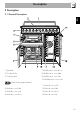
Description 2 Description EN 2.
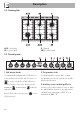
Description 2.2 Cooking hob AUX = Auxiliary SR = Semi-rapid R = Rapid UR2 = Ultra-rapid 2.3 Control panel 1 Hob burner knobs 2 Programmer clock For lighting and adjusting the hob burners. Press and turn the knobs anti-clockwise to in order to light the relative burners. Turn the knobs to the zone between the maximum and minimum setting to adjust the flame. For displaying the current time, setting programmed cooking operations and the minute minder timer.
Description The indicator light comes on to indicate that the auxiliary oven is heating up. It turns off as soon as it reaches the set temperature. It flashes regularly to indicate that the temperature set inside the oven is kept constant. 5 Multifunction oven temperature knob This knob allows you to select the cooking temperature and the Vapor Clean temperature. Turn the knob clockwise to the required value, between the minimum and maximum setting.
Description Interior lighting Oven tray The internal light of the appliance comes on when any function is started: • Multifunction oven: turn the function knob to any function (apart from the function ). • Auxiliary oven: turn the variable grill knob to the symbol or select a cooking temperature. • Vertical oven: turn the temperature knob to the symbol or select a cooking temperature. Useful for collecting fat from foods placed on the rack above.
Description Ring reducer EN Rack Useful when using small cookware. WOK ring Useful when using a wok. Used for supporting containers with food during cooking. Not all accessories are available on some models. Plate rack The accessories intended to come into contact with food are made of materials that comply with the provisions of current legislation. To be used for warming plates. Supplied and optional accessories can be requested to Authorised Service Centres.
Use 3 Use Instructions High temperature inside the oven during use Danger of burns • Keep the oven door closed during cooking. • Protect your hands wearing heat resistant gloves when moving food inside the oven. • Do not touch the heating elements inside the appliance. • Do not pour water directly on very hot trays. • Keep children under the age of 8 away from the appliance when it is in use.
Use • Do not spray any spray products near the oven. • Do not use or leave flammable materials near the oven or the storage compartment. • Do not use plastic cookware or containers for cooking. • Do not put sealed tins or containers in the oven. • Do not leave the oven unattended during cooking operations where fats or oils could be released. • Remove all trays and racks which are not required during cooking. Precautions A gas leak can cause an explosion.
Use 3.1 To save energy 3.2 Using the accessories • Preheat the appliance only if the recipe requires it. • Unless differently stated on the package, defrost frozen food before placing it in the cooking compartment. • In case of multiple cooking, it is recommended to cook food one after the other to exploit the already hot cooking compartment. • Use dark metal moulds: They help to absorb the heat better. • Remove all trays and racks which are not required during cooking.
Tray rack The tray rack has to be inserted into the tray. In this way fat can be collected separately from the food which is being cooked. Ring reducers The ring reducers must be placed on the hob grids. Make sure they are placed properly. Plate rack 1. Insert the plate rack without plates in the first shelf of the side oven. 2. Position the plates as shown in the figure. 3. Heat the oven to a temperature no greater than 50 °C for no more than 15 minutes. 4.
Use 3.3 Using the hob All the appliance’s control and monitoring devices are located together on the front panel. The burner controlled by each knob is shown next to the knob. The appliance is equipped with an electronic ignition device. Simply press the knob and turn it anticlockwise to the maximum flame symbol, until the burner ignites. If the burner does not light in the first 15 seconds, turn the knob to and wait 60 seconds before trying again.
Use Opening and closing the doors of the multifunction/vertical ovens The multifunction and vertical ovens are equipped with a swing door. To open, pull the door handle towards you. To close, push the doors until you hear a mechanical “click”. Switching on the multifunction oven Ensure that the programmer clock shows the cooking duration symbol , otherwise it will not be possible to turn on the oven. Press the keys and at the same time to reset the programmer clock. To switch on the multifunction oven: 1.
Use Multifunction oven functions Static As the heat comes from above and below at the same time, this system is particularly suitable for certain types of food. Traditional cooking, also known as static cooking, is suitable for cooking just one dish at a time. Perfect for all types of roasts, bread and cakes, and in any case, particularly suitable for fatty meats such as goose and duck.
Use Fan with round heating element The combination of the fan and the round heating element (incorporated in the rear of the oven) allows you to cook different foods on several levels, as long as they need the same temperatures and same type of cooking. Hot air circulation ensures instant and even distribution of heat. It will be possible, for instance, to cook fish, vegetables and biscuits simultaneously (on different levels) without odours and flavours mingling.
Use Switching on the auxiliary oven Switching on the vertical oven To switch on the auxiliary oven: • Select the temperature using the variable grill knob. The temperature ranges approximately from a minimum of 50 °C to a maximum of 245 °C. To switch on the vertical oven: • Turn the knob clockwise to select the required temperature between 50 °C and 245 °C. Vertical oven functions Auxiliary oven functions Light bulb Turns on the light inside the oven cavity.
3.5 Cooking advice General advice • Use a fan assisted function to achieve consistent cooking at several levels. • It is not possible to shorten cooking times by increasing the temperature (the food could be overcooked on the outside and undercooked on the inside). Advice for cooking meat • Cooking times vary according to the thickness and quality of the food and to consumer taste. • Use a meat thermometer when roasting meat, or simply press on the roast with a spoon.
Use Advice for defrosting and proving • Place frozen foods without their packaging in a lidless container on the first shelf of the oven. • Avoid overlapping the food. • To defrost meat, use the rack placed on the second level and a tray on the first level. In this way, the liquid from the defrosting food drains away from the food. • The most delicate parts can be covered with aluminium foil. • For successful proving, a container of water should be placed in the bottom of the oven.
Use If the time is not set, the oven will not switch on. On the first use, or after a power failure, the digits will be flashing on the appliance’s display. 1. Press the keys and at the same time. The dot between the hours and the minutes flashes. 2. The time can be set using or . Keep the key pressed in to increase or decrease rapidly. 3. Press the key or wait 5 seconds. The dot between the hours and the minutes stops flashing. 4.
Use It is not possible to set a cooking time of more than 10 hours. 3. Use the or key to set the required minutes. 4. Wait approx. 5 seconds without pressing any key in order for the function to activate. The current time and the After the setting, to display the cooking time left press the key. symbols and will appear on the display. 5. At the end of cooking the heating elements will be deactivated. On the 6. Press the keys and at the same time to reset the programmer clock.
Use The minute minder timer does not stop the cooking operation but rather informs the user when the set time has run out. The minute minder timer can be activated at any time. 1. Press the key. The display shows the digits and the indicator light Adjusting the buzzer volume The buzzer volume can be set to 3 different levels. When the buzzer is in operation, press the key to change the setting. Deleting the set data Press the keys and at the same time to reset the programs set.
Use Multifunction oven cooking information table Weight (kg) Function Level Temperature (°C) Time (minutes) Lasagne Pasta bake 3-4 3-4 Static Static 1 1 220 - 230 220 - 230 45 - 50 45 - 50 Roasted veal Pork loin Sausages Roast beef Roast rabbit Turkey breast Roast pork neck Roast chicken 2 2 1.5 1 1.5 3 2-3 1.
Use Food Sausages Pork chops Spare ribs Bacon Pork fillet Beef fillet Weight (kg) Function Level Temperature (°C) Time (minutes) 1.5 Grill 2 MAX 13 - 15 1.5 1.5 0.7 1.5 1 Grill Grill Grill Grill Grill 2 2 2 2 2 MAX MAX MAX MAX MAX 1nd surface 15 10 7 10 10 EN Auxiliary oven cooking information table 2nd surface 5 10 8 5 7 The times indicated in the table do not include preheating times and are provided only as a guide.
Cleaning and maintenance 4 Cleaning and maintenance Instructions Improper use Risk of damage to surfaces • Do not use steam jets to clean the appliance. • Do not use cleaning products containing chlorine, ammonia or bleach on parts made of steel or that have metallic surface finishes (e.g. anodizing, nickelor chromium-plating). • Do not use abrasive or corrosive detergents (e.g. scouring powders, stain removers and metallic sponges) on glass parts.
4.1 Cleaning the hob Igniters and thermocouples Cooking hob grids For correct operation the igniters and thermocouples must always be perfectly clean. Check them frequently and clean them with a damp cloth if necessary. Remove any dry residues with a wooden toothpick or a needle. Remove the grids and clean them in lukewarm water and non-abrasive detergent. Make sure to remove any encrustations. Dry them thoroughly and return them to the hob.
Cleaning and maintenance 4.2 Cleaning the doors The glass in the door should always be kept thoroughly clean. Use absorbent kitchen roll. In case of stubborn dirt, wash with a damp sponge and an ordinary detergent. 2. Grasp the door on both sides with both hands, lift it forming an angle of around 30° and remove it. Removing the door (auxiliary oven only) For easier cleaning it is recommended to remove the door and place it on a tea towel. To remove the door proceed as follows: 1.
Cleaning and maintenance Removing the internal glass panes For easier cleaning the internal glass panes of the door can be removed. 3. After removing the inner glass it is possible to access the drip catcher strip. EN Main oven door/ lateral 1. Remove the internal glass pane by pulling the top part gently, following the movement indicated by the arrows (1). 2. Then, pull the bottom part upwards (2). This way, the 4 pins attached to the glass detach from their housings in the oven door.
Cleaning and maintenance Auxiliary oven door 1. Remove the internal glass pane by pulling the rear part gently upwards, following the movement indicated by the arrows (1). 2. Then, pull the front part upwards (2). This way, the 4 pins attached to the glass detach from their housings in the door. 3. Remove the intermediate glass pane by lifting it upwards. 90 4. Clean the external glass pane and the panes removed previously. Use absorbent kitchen roll.
4.3 Cleaning the oven cavities Removing racks/trays support frames In order to keep your oven in the best possible condition, clean it regularly after letting it cool down. Avoid letting food residue dry inside the oven cavity, as this could damage the enamel. Take out all removable parts before cleaning.
Cleaning and maintenance Cleaning the upper part (multifunction and auxiliary ovens only) High temperature inside the oven during use Danger of burns • The following operations must be carried out only with the oven completely cold and turned off. The appliance is fitted with a tilting heating element that makes it easier to clean the top part of the oven. 1. Free the upper heating element by gently lifting it and rotating its retaining latch by 90 degrees. 4.
Cleaning and maintenance Vapor Clean setting 1. Turn the function knob to the symbol and the temperature knob to the symbol . 2. Set a cooking time of 18 minutes using the programmer clock. 3. At the end of the cooking time, the timer will switch the oven cavity heating elements off and the buzzer will start to sound. • Spray a water and washing up liquid solution inside the oven using a spray nozzle. Direct the spray against the side walls, upwards, downwards and towards the deflector. • Close the door.
Cleaning and maintenance 4.5 Extraordinary maintenance 4. Slide out and remove the light bulb. Replacing the internal light bulb Live parts Danger of electrocution • Unplug the appliance from the mains. The oven is fitted with a 40W light bulb. 1. Completely remove all accessories from inside the oven. 2. Remove the rack/tray support frames. 3. Remove the bulb cover using a tool (e.g. a screwdriver). Do not touch the halogen light bulb directly with your fingers, use an insulating material. 5.
Installing and removing the seal To remove the seal: • Unhook the clips in the 4 corners then pull the seal outwards. To refit the seal: • Hook the clips in the 4 corners onto the seal. Seal maintenance tips The seal should be soft and elastic. • To keep the seal clean, use a nonabrasive sponge and wash with lukewarm water. What to do if... The appliance does not work: • The switch is defective: check the fuse box to see whether the switch is in working order.
Installation 5 Installation 5.1 Gas connection Gas leak Danger of explosion • After carrying out any operation, check that the tightening torque of gas connections is between 10 Nm and 15 Nm. • If required, use a pressure regulator that complies with current regulations. • At the end of the installation, check for any leaks with a soapy solution, never with a flame.
Installation Connection with a steel hose Make the connection to the gas mains using a continuous wall steel hose whose specifications comply with the applicable standard. Carefully screw the connector 3 to the gas connector 1 of the appliance, placing the seal 2 between them. Connection with a steel hose with bayonet fitting Connection using a rubber hose complying with current standards is only permitted if the hose can be inspected along its entire length.
Installation Connection with a steel hose with conical fitting Make the connection to the gas mains using a continuous wall steel hose whose specifications comply with the applicable standard. Carefully screw the hose connector 3 to the appliance’s gas connector 1 (½” thread ISO 228-1), placing the supplied seal 2 between them. Apply insulating material to the thread of connector 3, then tighten the steel hose 4 to the connector 3.
Installation 5.2 Adaptation to different types of gas The appliance is preset for natural gas G20 at a pressure of 20 mbar. In case of operation with other types of gas, the burner nozzles must be changed and the minimum flame adjusted on the gas cocks. Replacing nozzles 1 Extraction using a hood 2 Extraction without a hood 1. Remove the grids, burner caps and flame-spreader crowns to access the burner cups. 2.
Installation Adjusting the minimum setting for natural or town gas Light the burner and turn it to the minimum position. Extract the gas cock knob and turn the adjustment screw next to the tap rod (depending on the model) until the correct minimum flame is achieved. Refit the knob and verify that the burner flame is stable. Turn the knob rapidly from the maximum to the minimum setting: The flame should not go out. Repeat the operation on all gas cocks.
Installation Gas types and Countries IT GB-IE FR-BE DE AT NL ES PT SE RU DK PL HU Gas types 1 Natural gas G20 20 mbar • • • • • • • • • • EN G20 • G20/25 20/25 mbar 2 Natural gas G20 G20 • 25 mbar 3 Natural gas G25 G25 25 mbar G25.3 25 mbar • • 4 Natural gas G25.1 G25.1 • 25 mbar 5 Natural gas G25 G25 • 20 mbar 6 Natural gas G2.350 G2.
Installation Burner and nozzle specifications tables 1 Natural gas G20 AUX SR R UR2 Rated heating capacity (kW) 1.0 1.8 2.9 4.2 Nozzle diameter (1/100 mm) 72 97 115 145 Pre-chamber (printed on nozzle) (X) (Z) (H9) (F3) Reduced flow rate (W) 400 500 800 1300 2 Natural gas G20 AUX SR R UR2 Rated heating capacity (kW) 1.1 1.8 2.9 4.
Installation AUX SR R Rated heating capacity (kW) 1.0 1.8 3.0 4.0 Nozzle diameter (1/100 mm) 50 65 85 100 - - - - Reduced flow rate (W) 400 500 800 1300 Rated flow rate G30 (g/h) 73 131 218 291 Pre-chamber (printed on nozzle) Rated flow rate G31 (g/h) UR2 71 129 214 286 8 LPG G30/31 AUX SR R UR2 Rated heating capacity (kW) 1.1 1.9 3.0 4.
Installation 5.3 Positioning Heavy appliance Crushing hazard • Position the appliance into the cabinet cut-out with the help of a second person. Pressure on the open door Risk of damage to the appliance • Never use the oven door to lever the appliance into place when fitting. • Avoid exerting too much pressure on the door when open. Any wall units positioned above the worktop of the appliance must be at a minimum distance of at least Y mm.
Installation EN Appliance overall dimensions B - Class 2 subclass 1 (Built-in appliance) A 900 mm B 600 mm C1 D min. 150 mm 900 - 915 mm H 750 mm I 450 mm L2 900 mm 1 Minimum distance from side walls or other flammable material. 2 Minimum cabinet width (=A). C - Class 2 subclass 1 (Built-in appliance) The appliance must be installed by a qualified technician and according to the regulations in force.
Installation Appliance dimensions Position of gas and electrical connections. Positioning and levelling Heavy appliance Risk of damage to the appliance • Insert the front feet first and then the rear ones. The appliance must sit level on the floor to ensure stability. • After making the gas and electrical connections, level and stabilise the appliance on the floor by screwing the foot in or out.
Installation Mounting the toe skirt The upstand provided is an integral part of the product; it must be fastened to the appliance prior to installation. The toe skirt provided is an integral part of the product; it must be fastened to the appliance prior to installation. The upstand must always be positioned and secured correctly on the appliance. 1. Loosen the 6 screws on the back of the hob (A) and unscrew the 2 screws (B) on the side part of the upstand.
Installation 5.4 Electrical connection Power voltage Danger of electrocution • Have the electrical connection performed by authorised technicians. • Use personal protective equipment. • The appliance must be connected to ground in compliance with electrical system safety standards. • Disconnect the mains power supply. • Do not pull the cable to remove the plug. • Use H05V2V2-F cables withstanding a temperature of at least 90 °C. • The tightening torque of the screws of the terminal board leads must be 1.
Installation • 220-240 V 3~ 4 x 4 mm² four-core cable. Fit the power line with an omnipolar circuit breaker in compliance with installation regulations. The circuit breaker should be located near the appliance and in an easily reachable position. Connection with plug and socket • 380-415 V 3N~ Make sure that the plug and socket are of the same type. Avoid using adapters, gang sockets or extensions as these could cause overheating and a risk of burns. 5 x 1.5 mm² five-core cable.
Installation 5.5 Instructions for the installer • The plug must be accessible after installation. Do not bend or trap the power cable. • The appliance must be installed according to the installation diagrams. • Do not try to unscrew or force the threaded elbow of the fitting. You may damage this part of the appliance, which may void the manufacturer’s warranty. • Use soap and water to check for gas leaks on all connections. DO NOT use naked flames to find leaks.