INSTALLATION, USER AND MAINTENANCE MANUAL FOR WATER OSMOSIS UNIT WO-01
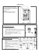
EQUIPMENT FOR POTABLE WATER TREATMENT CONTENTS: Paragraph GENERAL WARNINGS................................................................................................................. TECHNICAL CHARACTERISTICS ............................................................................................... POSITIONING AND INSTALLATION ............................................................................................ MAINTENANCE ..................................................................
1. General warnings STORAGE: THE PACKED APPLIANCE MUST BE STORED IN A DRY, CONDENSATION-FREE AREA, UNDER COVER. THE ADMITTED STORAGE TEMPERATURE IS 4-50°C. ALWAYS DISCONNECT ELECTRICAL POWER BEFORE WORKING ON THE APPLIANCE OR DISASSEMBLING IT. POSITIONING, HOOKUP, COMMISSIONING, TROUBLESHOOTING AND REPLACING POWER CABLES MUST ALWAYS BE DONE BY QUALIFIED PERSONS. CHANGES IN THE POWER VOLTAGE OF MORE THAN 10% OF THE RATED VALUE CAN DAMAGE THE ELECTRICAL CIRCUITS; MONITOR THE MAINS VOLTAGE CONSTANTLY.
THIS APPLIANCE IS MARKED AS REQUIRED BY EU DIRECTIVE 2002/96/EC, WASTE ELECTRICAL AND ELECTRONIC EQUIPMENT (WEE). BY MAKING SURE THAT THIS PRODUCT IS DISPOSED OF CORRECTLY THE USER HELPS TO PREVENT POTENTIAL DETRIMENTAL EFFECTS ON HEALTH AND THE ENVIRONMENT. THE SYMBOL ON THE PRODUCT OR IN THE TECHNICAL DOCUMENTATION INDICATES THAT THIS PRODUCT MUST NOT BE TREATED AS ORDINARY DOMESTIC WASTE BUT MUST BE CONSIGNED TO THE SPECIAL COLLECTION POINT FOR THE RECYCLING OF ELECTRICAL AND ELECTRONIC EQUIPMENT.
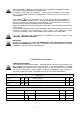
Technical characteristics Single phase power voltage 230 v Frequency 50 Hz Osmosis pump power rating 450 w Delivery pump power rating 300 w 150-600 (1.5-6) kPa (bar) Max osmosis-treated water output 150 l/h Max water supply temperature 30 °C Max water supply hardness 40 °F Max water supply conductivity 2.000 µS/cm Max water supply chlorine content <0.1 mg/l Max water supply iron content <0.02 mg/l Min/max delivery pump pressure 0.5-1.
3. Positioning and installation THE APPLIANCE MUST BE CONSIDERED AND HANDLED AS FRAGILE MATERIAL. THE CIRCUIT DOWNSTREAM OF THE UNIT MUST BE CONSTRUCTED IN PLASTIC AND STAINLESS STEEL TO PREVENT CORROSION. IF THE WATER SUPPLY CONTAINS PARTICLES IN SUSPENSION, AN EXTERNAL FILTER MUST BE INSTALLED TO PROVIDE SUFFICIENT DOWNSTREAM FLOW AND PRESSURE ; THIS FILTER MUST BE KEPT IN PERFECT CONDITION AT ALL TIMES .
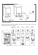
Water circuit and electrical hookup diagram Installing the membranes Open the front door to access the membrane housings, which must be kept in their original packaging until the machine is started up Disconnect the quick coupling hoses Undo the base Membrane mount - 34 - Fit the membrane Screw on the base Reconnect the hoses
Pressurizing and starting up the unit: After all pipes have been connected, pressurise the system gradually and check for leaks. Turn the “Osmosis pump” switch to “I”. Check that the following message displays: In normal operation the value Rj varies during osmosis-treated water production. Wait 5-10 minutes, then continue by starting up the delivery pump.
4. Maintenance The osmosis treatment unit runs completely automatically and maintenance is minimal. The only essential operation is periodic replacement of the filter cartridges. IMPORTANT Replace the pre-filter every 3000 hours of operation and AT LEAST 1 time a year.
Special adjustments: RECIRCULATION Recirculation retreats the waste water to reduce the amount of water rejected. Turn the needle valve “Recirculation” to retreat the waste water, thus reducing overall water consumption. Important! Make sure, when making adjustments, that the pressure gauge reading never exceeds 10-11 bar. BYPASS Turn the “Bypass” needle valve to adjust the conductivity of the osmosis-treated water, at the expense of the hourly water production and the amount of water rejected.
5.
LEGEND HYDRAULIC DIAGRAM IN E1 P1 FIL M1 SR VR MP SM MO CO Water inlet Filler solenoid valve Filler pressure switch Filter - CARBONLOK 5 micron Osmosis pump “Re-treatment” needle valve Non-return valve Pump pressure gauge Mixer needle valve Osmosis membrane Conductivity meter F1 P2 R M2 F2 E2 SS VE P3 SC PR Product flow meter Delivery minimum pressure switch Vat cock Delivery pump Waste flow meter Discharge solenoid valve Discharge choke Espansion tank Delivery pressure switch Water discarded Produced wa
6.
Electrical specifications: Power supply: 230v AC 50/60Hz Max motor outlet load: 16A_ at 230V AC Max load on solenoid valve 1 outlet: 1A_ at 230v AC Max load on solenoid valve 2 outlet: 1A_ at 230V AC Instrumentation: Conductivity meter (normalised at 20°C ) scale: 0-200uS/cm with probe K=5. Class (overall): 1 Calibrated by samples. Switchable display of uS/cm and mg/l; simply press the down button during operation.
6- Faults Front door leds The door has two leds to indicate: - Green: power on, normal operation; - Red: fault, production of osmosis-treated water stopped Important: THE DOOR GIVES NO INDICATION OF DELIVERY CIRCUIT FAULTS See below for details.
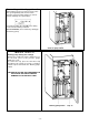
B) Osmosis-treated water not produced Possible causes Subcause Solution Check power supply and power switch ON (see “Positioning and installation”) No electrical power No power to pump Intake pressure switch faulty (jammed on full) Power plug not inserted in electrical panel (insert) Check connections and whether board is sending a signal Pump condenser faulty (replace) Replace, or adjust the pressure with the adjuster screw (fig.
C) Water production not conforming Display alarm message Cause of alarm Solution Adjust "bypass" needle valve The treated water does not conform with settings HHHH Replace membranes Replace pre-filter (see maintenance section) LLLL The water production is below the set value Replace membranes (see maintenance section) Adjust "bypass" needle valve Figures Pressure switch Fig.1 Delivery pressure switch with adjust screw Fig.
Non-return valve Fig.3 Vat cock Fig.4 Pressure switch Solenoid valve Filter Fig.
7. Electronic circuit board and programming Hold down F1 and press ENTER to enter conductivity programming. We can now read the calibrated value. Press UP/DOWN to set the value. Press ENTER to save and quit. Press F1 to abort without saving.
Display: In standby (system not running) : Pressing F1 runs a water flushing cycle. X.X indicates the software version (e.g. 2.1) After a few minutes, switch off and on again with the osmosis pump switch. In stand by: hold down UP/DOWN together to enter programming mode: (in all the following procedures: UP/DOWN changes the value, ENTER saves and continues, F1 continues without saving). Programming procedures: >>>>>>>>>>>>>>>>>>>>>>>> X.X indicates the software version (e.g. 2.
Press ENTER or F1: Stop motore se in moto per … (Stop motor after …) The following two messages concern the osmosis pump motor condition. Set = 0 to exclude this mode; if the value is not 0, the motor stops running after having run continuously for the set period, then starts again. After two seconds, the system displays:>>>>>>>>>>>>>> Press ENTER or F1: If the conductivity value remains below set value, no alarm trips, otherwise an alarm displays.
Press ENTER or F1; the system returns to standby. The switch at the top of the display, if pressed to the right, switches from the waste water flow display - 49 - to the osmosis-treated water flow display. When it is released, the display returns to waste water flow mode.