Built-in Hotplate, Ovens, Stoves, Minigrills, Hotplate-Sink Combos for Recreational Vehicles and Marine. Models: CU311 - CU311M - CU333 - CU333M - CU335 CU335M - CU401 - CU401PE - CU402 - CU402PE - CU403 - CU403PE - FO311 - MO8103 - MO8123 PI0913 - PI0913A - PI8002 - PI8022 - PI8003 - PI8023 - PI8403 - PI8403GL - PI8423 - PI8423GL - PI8443 PI8463 - PI8621A - PI8621S - PI8621R - VN555 LIBR51 REV.
EN CONTENTS CONTENTS 1 GENERAL INFORMATION ................................................................. 3 1.1 1.2 Symbols used in this manual ........................................................................................................3 Using and keeping the manual ...................................................................................................3 2. WARNINGS .......................................................................................... 4 3. USE ........
1. 1 GENERAL INFORMATION 1.1 Symbols used in this manual GENERAL INFORMATION Below are shown the various symbols used in the manual to highlight particularly important information. The safety symbols draw attention to potential hazards for personal safety. Absolutely respect all safety messages by following these symbols. WARNING Risk of injury or death. WARNING CAUTION To avoid possible injuries and/or malfunctions. CAUTION 1.
IT EN 2. 2. WARNINGS WARNINGS Do not use or store flammable materials in the appliance storage drawer or near this appliance. Do not spray aerosols in the vicinity of this appliance while it is in operation. Do not modify this appliance. Where this appliance is installed in marine craft or in caravans, it shall NOT be used as a space heater.
EN 3. USE 3. USE 3.1 Precautions CAUTION This appliance must only be used by responsible adults. During use and immediately after use the burner and other accessible parts may be hot; do not touch these parts and always keep children at a safe distance. After using the appliance ensure the knob/knobs are off. CAUTION After use always shut off the gas supply at the main gas tap.
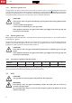
IT EN 3. USE The following symbols are for burner flame regulation and correspond to the position of the knob. NOTE: Different models could have similar knobs and symbols.
EN 3. USE 3.3.2 Electronic ignition hotplate (depending on model) WARNING Make sure there are no pans or any other objects on the burners when igniting. WARNING To ignite the burner, gently push in and turn the control knob to position HIGH FLAME and, keeping the knob pushed in, at the same time press the electronic ignition pushbutton. Once the burner is lit, keep the knob pushed in for a few seconds to ensure the flame remains lit.
IT EN 3. USE 3.4.1 Electronic ignition oven To ignite the burner, push in and turn the control knob to a position from 1 to 6 and, keeping the knob pushed affixed to the oven door in, at the same time press the electronic ignition pushbutton (for models that have the electronic ignition button is not visible and is activated by pressing the gas knob down). Once the burner is lit, keep the knob pushed in for a few seconds to ensure the flame remains lit.
EN 3. USE When using the grill the door must be kept open and with the heat guard fully extracted (FIG. 1 – PG. 19). Never use the grill for more than 25 minutes.The grill cannot be used as an oven. If the burner flame goes out accidentally, turn off the gas knob and wait one minute before re-igniting. 3.5.1 Electronic ignition grill WARNING Do not ignite the grill burner with the door closed.
IT EN 3. USE 3.6 Electric hotplate (depending on model) CAUTION Before turning on the electric hotplate (or if the hotplate has remained unused for a long time) it is necessary to eliminate any moisture by turning on the hotplate and leaving it on for 30 minutes with the corresponding knob in position 1. CAUTION Use pans with flat bottoms and with diameters no less than the diameter of the hotplate. Dry the bottom of the pan before placing it on top of the hotplate.
EN 3. USE CAUTION Hot surfaces may be damaged on contact with cold water or with a wet cloth. Do not use abrasive, corrosive or chlorine-based products, pot scourers or steel wool. Do not leave acid or alkaline substances (vinegar, salt, lemon juice, etc.) on the surfaces of the appliance. Stainless steel surfaces and enamelled parts must be washed with water and neutral soap or detergent, rinsed and dried. Use clean sponges and cloths.
IT EN 4. 4.1 INSTALLATION Dimensions of the appliance The overall dimensions are illustrated in FIG. 5 - PG. 21 with the cavity diagrams. The overall dimensions include the trivet (pan support), control knobs, handles and gas connection. 4.2 Fitting cavity WARNING The appliance must fitted at an appropriate and safe distance from flammable materials. WARNING WARNING WARNING For the CU..., FO... and VN555 models, the cavity that the appliance is built into must be completely sealed off.
4. INSTALLATION WARNING The appliance is not suitable for connection with a hose assembly. WARNING WARNING A manual shut-off valve shall be provided on the inlet connection of the appliance. The valve shall be accessible for operation and firmly fixed. WARNING Below are the gas characteristics for which the appliance is set (given also on the appliance data plate).
IT EN 4. INSTALLATION NOMINAL GAS CONSUMPTION AUXILIARY SEMI-RAPID Model PI8443 PI8463 PI8621A PI8621R PI8621S VN555 Ø 47 mm MJ/h № 1 3.8 1 3.8 1 3.8 Ø 62 mm MJ/h № 2 5.9 2 5.9 RAPID Ø 77 mm MJ/h № 1 1 Grill № MJ/h 7.2 5.9 1 5.2 TOTAL NOMINAL GAS Oven CONSUMPTION MJ/h № MJ/h 15.6 15.6 3.8 7.2 5.9 5.2 BURNER INJECTOR ORIFICE (mm) STAMPED № AUXILIARY (Ø 47mm) 0.57 57 SEMI-RAPID (Ø 62mm) 0.72 72 RAPID (Ø 77mm) 0.80 80 GRILL 0.67 67 OVEN 0.
4. INSTALLATION To connect the appliance use a 1.5 mm2 double red and black wire and wire to the terminal junction box – “. The red terminal is the positive pole and located at the rear of the appliance with the wording “+12 V the black terminal is the negative pole. High voltage 230-240 V~ This chapter refers only to the models listed in the table below. Model Nominal voltage Nominal power CU401PE - CU402PE - CU403PE 230-240V~ 800 W In these models there is an electric plate in the hotplate.
IT EN 4. INSTALLATION 4.6.1 Test point For models PI... MO... CU... The test point is supplied loose with the appliance (see picture in FIG. 7 - PG. 31). Remove one burner head, the injector and screw in test point fitting.The pressure is measured with the relevant burner gas valve on high flame and with an inlet pressure of 2.75 kPa. For models FO... The test point is fitted on the main gas pipe. Remove the front plastic plaque (see picture in FIG. 8 - PG. 31) and remove the screw.
5. SERVICING 5 SERVICING WARNING The servicing shall be carried out only by authorized personnel. WARNING WARNING Do not modify this appliance. WARNING WARNING Before any servicing intervention shut off gas supply, disconnect all the electrical power supplies and remove the appliance. WARNING Hotplate: burners, injectors, thermocouples and ceramic igniters 1. Remove trivet (pan support) by pulling up from hotplate. 2. Remove screws from appropriate burner head disk. Remove head disk. 3.
IT EN 5. SERVICING 9. Remove the ceramic igniter. 10. Remove the grill burner mounting screws (2) from top. 11. Remove the grill burner mounting spacers (only for CU4... models) and lower burner. Gas cocks 1. Remove the control knob by pulling. 2. Unscrew gas cock retaining nut. 3. From the underside of the appliance, remove the thermocouple lead and the gas pipe from the gas cock. 4. Remove the appropriate gas cock clamp by unscrewing the screws. 5. Remove the gas cock from the manifold. 6.
FIGURES AND TECHNICAL DRAWINGS FIGURES AND TECHNICAL DRAWINGS Figure 1 Figure 2 Figure 3 19 EN
IT EN FIGURES AND TECHNICAL DRAWINGS Figure 4 200 mm 200 mm CU311 - CU311M - CU333 - CU333M - CU335 - CU335M - CU401 CU401PE - CU402 - CU402PE - CU403 - CU403PE - MO8103 MO8123 - PI0913 - PI0913A - PI8002 - PI8022 - PI8003 - PI8023 - PI8403 PI8403GL - PI8423 - PI8423GL - PI8443 - PI8463 - PI8621A - PI8621S - PI8621R 600 mm 100 mm FO311 - VN555 170 mm 100 mm 20
FIGURES AND TECHNICAL DRAWINGS Figure 5 50 3m m 2 52 mm 428 mm CU311 CU333 CU335 FRONT VIEW SIDE VIEW 415 mm 393 mm 393 mm 500 mm MIN. 45 mm MIN.
IT EN FIGURES AND TECHNICAL DRAWINGS CU401 CU401PE TOP VIEW FRONT VIEW SIDE VIEW 488 mm 479 mm mm 514 mm 592 mm 535 MIN. 494 mm 591 mm 601 mm 591 mm 601 mm MIN. 21 mm 25 mm 20 mm 488 mm 20 mm MIN. 500 mm CU402 CU402PE TOP VIEW MIN. 494 mm FRONT VIEW SIDE VIEW 488 mm 479 mm 281 mm 281 mm 488 mm 20 mm m 4m mm 51 292 mm 535 MIN. 21 mm MIN. 500 mm 20 mm CU403 CU403PE 51 0m 143 mm TOP VIEW 488 mm 22 20 mm FRONT VIEW SIDE VIEW 488 mm 479 mm 132 mm 132 mm MIN.
EN FIGURES AND TECHNICAL DRAWINGS FO311 50 3m 528 478 mm m mm FRONT VIEW SIDE VIEW MIN.
IT EN FIGURES AND TECHNICAL DRAWINGS 273 mm 440 mm mm 13 5° 13 5° 0 56 mm mm 80 mm R30 214 mm 30 1 m m R30 273 mm R30 mm mm 0 R3 PI8003 PI8023 30 1 m m 214 mm 428 mm R7 m m 0 m R7 0 m 546 mm PI8403 - PI8403GL PI8423 - PI8423GL PI8443 - PI8463 572 mm 199 mm 35 220 mm 205 mm 0m m 76 mm A 140 mm 76 mm 135° 54 mm 25 mm A 55 mm 92 mm 90° m R3 11 m 70 mm 130 mm m 5m 216 mm mm R5 332 mm 0 59 m 1m R531 mm R7 70 mm m m 202 mm 5 8, 199 mm SEZ.
EN FIGURES AND TECHNICAL DRAWINGS MO8103 MO8123 430 956 mm 478 mm A 0 m 90° 129.8 mm R3 R3 0 m m 0m R3 0 421.7 mm 10 mm 0 R3 R3 448 mm 421.7 mm 0 mm 10 448 mm mm 140 mm 478 mm 8 96 R3 54.9 mm 416 mm 208 mm 178 mm 5 mm 208 mm 3m R20 285.7 mm R16 A 7m m m 45 mm 3m R2 5 151.7 mm 54.9 mm 178 mm 178 mm 135° 253 mm m 178 mm 29.8 mm R3 0 151.7 mm 10 135° 33.9 mm 225 mm SEZ. A-A 275 mm 47 5m m 484 mm FRONT VIEW SIDE VIEW 486 mm MIN. 460 mm MIN.
IT EN FIGURES AND TECHNICAL DRAWINGS Figure 6 CU311 CU333 CU335 CU311M CU335M CU333M 26 190 mm 210 mm
FIGURES AND TECHNICAL DRAWINGS CU401 CU401PE CU402 CU402PE CU403 CU403PE 27 EN
IT EN FIGURES AND TECHNICAL DRAWINGS FO311 PI0913 PI0913A PI8621A PI8621R PI8621S 28
FIGURES AND TECHNICAL DRAWINGS PI8002 PI8022 PI8003 PI8023 ≥ 21 mm X ≤ 25 mm ≥ 16 mm Y ≤ 21 mm X PI8403 - PI8403GL PI8423 - PI8423GL PI8443 - PI8463 29 EN
IT EN FIGURES AND TECHNICAL DRAWINGS MO8103 MO8123 X X VN555 30 ≥ 21 mm ≤ 25 mm Y ≥ 16 mm ≤ 21 mm
FIGURES AND TECHNICAL DRAWINGS Figure 7 Figure 8 31 EN
IT EN FIGURES AND TECHNICAL DRAWINGS Figure 9 32
Notes ..................................................................................................................................................................................................... ..................................................................................................................................................................................................... ..............................................................................................................
..................................................................................................................................................................................................... ..................................................................................................................................................................................................... ....................................................................................................................
WHO TO CONTACT For service of your appliance, firstly contact your selling agent. Australia Dometic Australia, Queensland 1 Dometic Australia,Victoria 1 John Duncan Court Bldg 3B, Clayton Business Park Varsity Lakes QLD 4227 1508 Centre Rd, Clayton VIC 3168 phone: +61 (0)7 5507 6000 phone: +61 (0)3 9239 1000 fax: fax: +61 (0)7 5507 6001 +61 (0)3 9239 1099 e-mail: sales@dometic-waeco.com.au e-mail: sales@dometic-waeco.com.au web: web: www.dometic-waeco.com.au www.dometic-waeco.com.