
Operating Instructions and Installation Instructions

5. SERVICING
EN
17
5 SERVICING
WARNING
WARNING
The servicing shall be carried out only by authorized personnel.
WARNING
WARNING
Do not modify this appliance.
WARNING
WARNING
Before any servicing intervention shut off gas supply, disconnect all the electrical
power supplies and remove the appliance.
Hotplate: burners, injectors, thermocouples and ceramic igniters
1. Remove trivet (pan support) by pulling up from hotplate.
2. Remove screws from appropriate burner head disk. Remove head disk.
3. Remove burner by lifting straight up, taking care not to damage the thermocouple and ceramic igniter.
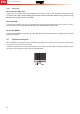
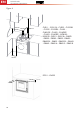
4. Using a 7mm spanner, unscrew the injector. When removing and fitting the injector, the injector holder
must be held in place with the aid of a tool (FIG. 9 - PG. 32)
5. Remove retaining washer from thermocouple head.
6. Disconnect appropriate thermocouple lead from gas cock.
7. Remove the thermocouple.
8. Remove retaining spring from ceramic igniter head.
9. Disconnect appropriate ceramic igniter lead from electronic igniter unit.
10. Remove the ceramic igniter.
11. Replace/ refit in reverse procedure.
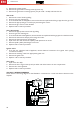
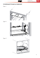
Oven: injector, burner, thermocouple and ceramic igniter
1. From right hand side of appliance, remove spring from the oven burner inlet.
2. Using a 7mm spanner, unscrew the injector. When removing and fitting the injector, the injector holder
must be held in place with the aid of tool (FIG. 9 - PG. 32).
3. Remove lower heat shield at rear and tilt appliance forward.
4. Unscrew the oven burner mounts and lower burner.
5. Remove retaining nut from thermocouple head.
6. Disconnect the oven thermocouple lead from the gas cock.
7. Remove the thermocouple.
8. Remove retaining screw from ceramic igniter support.
9. Disconnect ceramic igniter lead from appropriate electronic igniter unit.
10. Remove the ceramic igniter.
11. Replace/ refit in reverse procedure.
Grill: injector, thermocouple, ceramic igniter and burner
1. From right hand side of appliance, remove spring from the grill burner inlet.
2. Using a 7mm spanner, unscrew the injector. When removing and fitting the injector, the injector holder
must be held in place with the aid of tool (FIG. 9 - PG. 32)
3. Remove the protection disk (not present in the CU4... models)
4. Remove retaining nut from thermocouple head.
5. Disconnect the grill thermocouple lead from the gas cock
6. Remove the thermocouple.
7. Remove retaining screw from ceramic igniter support.
8. Disconnect ceramic igniter lead from appropriate electronic igniter unit.