
Operating Instructions and Installation Instructions

5. SERVICING
18
IT
EN
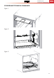
9. Remove the ceramic igniter.
10. Remove the grill burner mounting screws (2) from top.
11. Remove the grill burner mounting spacers (only for CU4... models) and lower burner.
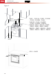
Gas cocks
1. Remove the control knob by pulling.
2. Unscrew gas cock retaining nut.
3. From the underside of the appliance, remove the thermocouple lead and the gas pipe from the gas cock.
4. Remove the appropriate gas cock clamp by unscrewing the screws.
5. Remove the gas cock from the manifold.
6. Replace/ refit in reverse procedure.
Oven thermostat
1. Remove the appropriate control knob by pulling.
2. Unscrew gas cock retaining nut.
3. From the underside of the appliance, remove the thermocouple lead and the gas pipe from the thermostat.
4. Remove the thermostat clamp by unscrewing the screws.
5. Remove the thermostat from the manifold.
6. Open oven door and remove the capillary bulb/ phial from its mount.
7. Remove capillary bulb/ phial though access hole.
8. Replace/ refit in reverse procedure.
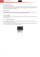
Igniter unit/s
1. From the rear right-hand side of appliance, remove electrical connectors from igniter unit/s (noting
connection locations).
2. Remove the retaining rivets from appropriate igniter unit.
3. Remove the igniter unit.
4. Replace / refit in reverse procedure.
Oven door
1. Open oven door fully.
2. Remove the door hinge screws (2 each) at either side of the bottom of oven compartment.
3. Remove door from appliance.
4. Replace/ refit in reverse procedure.
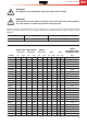
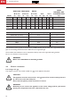
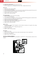
230-240 V~ WIRING DIAGRAM
Shown below is the wiring diagram for the 230-240 V~ connection for a stove with electric element on the
hotplate.
3
3