GTIOM-3 MODEL GT SERIES INSTALLATION, OPERATING AND MAINTENANCE MANUAL Modulating, Direct Vent, Gas-Fired Condensing Boilers Natural Or Propane 150,000 to 399,000 Btuh Input see note gama ENERGY STAR WARNING: If the information in this manual is not followed exactly, a fire or explosion may result causing property damage, personal injury or loss of life. Do not store or use gasoline or other flammable vapors and liquids in the vicinity of this or any other appliance.
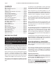
Page 2 GT INSTALLATION AND OPERATION INSTRUCTIONS CONTENTS Before You Start ................................................. page 2 Boiler Ratings & Capacities ............................... page 2 Boiler Location ................................................... page 3 Clearances to Combustible Construction .......... page 3 Combustion Air .................................................. page 4 General Venting Guidelines ............................... page 4 Horizontal Direct Vent Systems ........
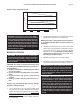
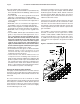
GT INSTALLATION AND OPERATION INSTRUCTIONS Page 3 Figure 1- Input vs Elevation Graph 400 Input (Mbh) 300 200 100 0 0-2000 GT-150 3000 4000 5000 GT-200 WARNING: At elevations greater than 2000 ft, 660 m, the combustion of the GT must be checked with a calibrated combustion analyzer to ensure safe and reliable operation. Consult the Operating Instructions Section for instructions on adjusting the input to provide proper operation.
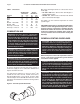
Page 4 GT INSTALLATION AND OPERATION INSTRUCTIONS Table 1 - Clearances Surface Front Back Sides Top Bottom - 150 & 200 Bottom - 400 Flue Pipe - enclosed Flue Pipe - in free air Combustible Clearance in mm 0 0 0 0 0 0 0 0 0 0 0 0 2 51 0 0 Service Clearance in mm 24 610 0 0 12 305 12 305 12 305 0 0 n/a n/a n/a n/a COMBUSTION AIR WARNING: This boiler must be supplied with combustion air in accordance with Section 5.
GT INSTALLATION AND OPERATION INSTRUCTIONS The GT condensing gas boiler is a high efficiency boiler utilizing induced power venting. It is designed to be vented directly to the outdoors using the venting methods and materials detailed in this section. The vent system must be both gas tight and watertight. All horizontal vent piping must be sloped back to the boiler a minimum of 1/4 in/ft, 21mm/m of vent.
Page 6 GT INSTALLATION AND OPERATION INSTRUCTIONS The vent terminal shall not terminate: • Directly above a paved sidewalk or a paved drive-way that is located between two buildings, and that serves both buildings; • Less than 7 ft, 2.1 m above grade where located adjacent to a paved driveway or public walkway. • Within 3 ft, 0.9 m, horizontally of a window or door that can be opened, or non-mechanical air supply inlet to any building. • Within 6 ft, 1.
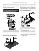
GT INSTALLATION AND OPERATION INSTRUCTIONS When penetrating an outside wall the air intake and vent pipes must be constrained as shown in Figure 6. The openings through which the air intake and vent pipes pass must be properly sealed to prevent products of combustion from entering the building.
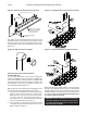
Page 8 GT INSTALLATION AND OPERATION INSTRUCTIONS Figure 9 - External Air Intake and Vent Systems Figure 11- Horizontal Concentric Terminal Location SUPPORTS EVERY 24 IN EXHAUST INLET 20 FOOT MAX OUTSIDE USING ONLY 3" PIPE ON THE 150 & 200 AND 4" PIPE ON THE 400 12 IN ABOVE MAXIMUM SNOW LINE The debris screens provided with the boiler must be installed in both the air intake and vent terminals.
GT INSTALLATION AND OPERATION INSTRUCTIONS Figure 13 - Wall Penetration Detail Page 9 Consult your weather office for the maximum typical snowfall for your region. For example, in Boston MA the maximum typical snowfall is 12 in, 305 mm. Therefore the inlet must be 24 in, 610 mm, above any surface that will support snow. The exhaust must be 42 in, 1067 mm, above this surface.
Page 10 GT INSTALLATION AND OPERATION INSTRUCTIONS Install and seal a rain cap over the dormant chimney opening to prevent water from entering the building. Use only ABS, PVCsch.40, CPVC, or AL294C pipe for the air inlet and vent systems as stated previously. Ensure that the air inlet and vent system lengths are within the maximums specified in Table 2.
GT INSTALLATION AND OPERATION INSTRUCTIONS The following are important rules that must be followed when constructing the condensate system: 1. Connect the condensate trap to the drain using 1/2 in, 13 mm, silicone, rubber, reinforced nylon, or PEX tubing. Long runs must be properly pitched and supported to prevent blockage. 2. Do not use nylon tubing, as it will collapse, blocking drainage. This could damage the boiler. 3.
Page 12 GT INSTALLATION AND OPERATION INSTRUCTIONS Understand and follow the plumbing requirements provided in this section. Keep serviceability in mind when installing plumbing around the boiler cabinetry. Install fittings that will allow the system to be flushed if needed during annual check-ups. Add an inhibitor to the system water to prevent lime and magnetite deposits from forming, and to protect the boiler from galvanic corrosion.
GT INSTALLATION AND OPERATION INSTRUCTIONS Figure 22 - Boiler Head Loss GT-150 Feet of Head Low Water Cut Off, LWCO If a LWCO is used ensure that the water line of the “Low Water Cutoff” is at least 6 in, 152 mm, above the top of the boiler, Figure 21. It is recommended that the LWCO be situated so that it can be tested without removing water from the boiler. Tri-cocks and a gauge glass are highly recommended. Valves shall not be installed between the LWCO and the boiler.
Page 14 GT INSTALLATION AND OPERATION INSTRUCTIONS Figure 23 - Single Boiler with Indirect Hot Water Heater NOTES: 1. All piping and pumps must be supported so that no loads or stresses are applied to boiler heat exchanger. To make boiler service easy use Unions or flexible Vibration Isolation Kit. 2. This boiler is provided with a 1/8" vent that is not intended for continuous system venting. 3. For continuous system venting use a cast iron air scoop, for excessive air conditions use a Spirovent.
GT INSTALLATION AND OPERATION INSTRUCTIONS Page 15 Figure 24 - Multiple Boiler Installation NOTES: 1. All piping and pumps must be supported so that no loads or stresses are applied to boiler heat exchanger. To make boiler service easy use Unions or flexible Vibration Isolation Kit. 2. This boiler is provided with a 1/8" vent that is not intended for continuous system venting. 3. For continuous system venting use a cast iron air scoop, for excessive air conditions use a Spirovent.
Page 16 GT INSTALLATION AND OPERATION INSTRUCTIONS Figure 25 - Multiple Zones Using Circulators NOTES: 1. All piping and pumps must be supported so that no loads or stresses are applied to boiler heat exchanger. To make boiler service easy use Unions or flexible Vibration Isolation Kit. 2. This boiler is provided with a 1/8" vent that is not intended for continuous system venting. 3. For continuous system venting use a cast iron air scoop, for excessive air conditions use a Spirovent.
GT INSTALLATION AND OPERATION INSTRUCTIONS Page 17 Figure 26 - Multiple Zones Valves with Bypass Valve Note: Velocity noise may be a problem when the entire output of the system pump is flowing through the zone with the highest pressure drop. Adjust the differential bypass valve to eliminate noise. NOTES: 1. All piping and pumps must be supported so that no loads or stresses are applied to boiler heat exchanger. To make boiler service easy use Unions or flexible Vibration Isolation Kit. 2.
Page 18 GT INSTALLATION AND OPERATION INSTRUCTIONS GAS SUPPLY PIPING The GT hot water boiler comes from the factory ready to be piped to the gas supply. The National Fuel Gas Code, ANSI Z223.1/NFPA 54 and local codes for gas piping requirements and sizing must be followed. If for any reason the boiler is not for the type of gas available at the installation site, call the nearest Smith distributor to resolve the problem. Figure 27 depicts the proper way to connect the boiler to the gas supply piping.
GT INSTALLATION AND OPERATION INSTRUCTIONS ELECTRICAL WIRING CAUTION: Label all wires prior to disconnection when servicing controls. Wiring errors can cause improper and dangerous operation! The electrical connections to this boiler must be made in accordance with all applicable local codes and the latest revision of the National Electrical Code, ANSI/ NFPA-70. Install a separate 120 volt 15 amp circuit for the boiler, Figures 28 and 29. A properly rated shutoff switch should be located at the boiler.
Page 20 GT INSTALLATION AND OPERATION INSTRUCTIONS Figure 29 - Basic Heating System and Indirect Tank Wiring Multiple 4 Wire Zone Valves Figure 30 shows the basic multiple zoned system uses normally closed four (4) wire zone valves. This wiring system is used with the piping shown in Figure 26. When there is a call for heat the room thermostat closes the circuit to the zone valve motor, thus opening the zone valve.
GT INSTALLATION AND OPERATION INSTRUCTIONS Figure 30 - Multiple 4 Wire Zone Valves Page 21
Page 22 GT INSTALLATION AND OPERATION INSTRUCTIONS Figure 31 - Multiple Zones w/ Taco Valve Controller, Models ZVC403 to ZVC 406
GT INSTALLATION AND OPERATION INSTRUCTIONS Multiple Zone Pump Controller Models Taco SR504, Argo ARM 861 Series Figure 32 shows the basic multiple zoned system using circulating pumps. This wiring system is used with the piping as shown in Figures 25. Page 23 Once the room thermostat is satisfied, it breaks power to the TT terminal of the pump controller de-energizing the XX contacts. The circuit between terminals T and C opens shutting down the pumps and the burner.
Page 24 GT INSTALLATION AND OPERATION INSTRUCTIONS Figure 33 - Boiler Ladder Diagram
GT INSTALLATION AND OPERATION INSTRUCTIONS Figure 34 - Boiler Connection Diagram Page 25
Page 26 GT INSTALLATION AND OPERATION INSTRUCTIONS SENTRY 2100T CONTROLLER Figure 37 - 2100T Display Screen CAUTION: The T4.0 controller can only be used on the GT-400 and the T2.0 on the GT-150 & 200. Misapplication of the controller will result in improper boiler operation. The Sentry 2100T controller is the central controller for the GT boiler. The Sentry handles all of the combustion logic, along with the energy management functions.
GT INSTALLATION AND OPERATION INSTRUCTIONS Page 27 Figure 38 - Input Conversion Chart Display Data - Input conversion chart 400 350 GT-150 GT-400 BTU (000's) 300 GT-200 250 200 150 100 50 0 240 215 190 165 140 115 90 65 48 40 LED Display Setting Sentry 2100T control Programming is accomplished by a series of three push buttons located on the bottom side of the control. To enter the programming mode, press the function key once, “RUN” should be displayed on the screen.
Page 28 GT INSTALLATION AND OPERATION INSTRUCTIONS Determining Reset Temperature HICalc Once the Sentry 2100T control identifies the presence of a good outdoor sensor, the control will automatically reduce the HI setting based upon the outdoor temperature. For example, if Hi = 200°F, 93°C, RES = 70°F, 21°C and the Air Temperature = 32°F, 0°C, the HI setpoint, HICalc, would be calculated as follows: RESET RATIO = (High Setting - RES)/RES = (200°F, 93°C - 70°F, 21°C) /70°F, 21°C = 1.
GT INSTALLATION AND OPERATION INSTRUCTIONS BOILER SET UP NOTE: Before starting the boiler, turn off the electrical supply going to it. Make sure that gas is available at the gas valve inlet. Open the valves in the hot water return and supply piping. Failure to take these precautions will prevent the boiler from operation properly. Fill the boiler and all of the radiation with water. Make sure that the system is completely purged of air, see GENERAL PLUMBING GUIDELINES.
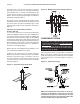
Page 30 GT INSTALLATION AND OPERATION INSTRUCTIONS The gas supply pressure to the boiler while running at maximum rate must be between 4 to 9 in, 102 to 229 mm, W.C. for natural gas installations; 9 to 12 in, 229 to 305 mm, W.C. for propane installations. This pressure can be measured on the gas valve using a manometer, Figure 41 or 42. Ensure that the regulator is capable of maintaining this pressure under all operating conditions.
GT INSTALLATION AND OPERATION INSTRUCTIONS Page 31 Figure 43 - Operational Flow Chart 120v Power Applied Combi model Energizes 3 way diverter valve Indirect thermostat or flow switch closes A-C (Call for Domestic) Combi or indirect Indirect Water Heater Energizes Primary Pump (C1) Boiler in standby Mode Displays version t2.0 or t4.
Page 32 GT INSTALLATION AND OPERATION INSTRUCTIONS FOR YOUR SAFETY READ BEFORE OPERATING WARNING: If you do not follow these instructions exactly, a fire or explosion may result causing property damage, personal injury or loss of life. A. This appliance does not have a pilot. It is equipped with an ignition device which automatically lights the burner. Do not try to light the burner by hand. B. BEFORE OPERATING smell all around the appliance area for gas.
GT INSTALLATION AND OPERATION INSTRUCTIONS BOILER CHECKING & ADJUSTMENT Input Rate Gas appliances are rated based on sea level operation with no adjustment required at elevations up to 2000 ft, 610 m. At elevations above 2000 ft, 610 m, input ratings should be reduced by 4% for each 1000 ft, 305 m, above sea level. Check the input rate as follows: NATURAL GAS: 1. Turn off all other gas appliances that use the same gas meter as the boiler. 2. Call the gas company for the gas heating value. 3.
Page 34 GT INSTALLATION AND OPERATION INSTRUCTIONS BOILER MAINTENANCE The boiler should be cleaned and inspected once a year, before each heating season. CAUTION: Servicing, inspection and adjustment must be done by a trained technician in accordance with all applicable local and national codes.
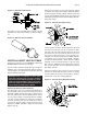
GT INSTALLATION AND OPERATION INSTRUCTIONS Figure 46 - Gas Valve Rotation NEW LOCATIONS FOR SCREWS out Aquastat High Limit The aquastat high limit controls the maximum water temperature in the boiler. If the water temperature reaches the set temperature before the demand for heat has been met, the aquastat high limit should shut the burners off. The outlet water temperature should never exceed 220°F, 104°C. If the aquastat high limit fails to function properly replace it.
Page 36 GT INSTALLATION AND OPERATION INSTRUCTIONS TROUBLE SHOOTING This section is intended to assist the service technician in detecting and correcting common errors. The Sentry 2100 is equipped with an internal diagnostic system that verifies control operation. The following series of error codes has been developed to aid in diagnosing control problems: Problem Detected Problem Solution ER1 On Display The Safety High Limit of 215°F, 102°C, has been reached. 1.
GT INSTALLATION AND OPERATION INSTRUCTIONS Problem Detected Problem Page 37 Solution ASO Indicates that the Air Switch is Open This is displayed when the boiler is expecting the air switch to be closed by a differential pressure generated when the combustion blower turns on. It can occur momentarily during normal operation. A problem is indicated when ASO is displayed continuously. 1. Are the vinyl tubes connected between the air switch and the ports on the inlet pipe.
Page 38 GT INSTALLATION AND OPERATION INSTRUCTIONS Problem Detected Problem Solution Ignition Sequence not activated when burner light is on (Fan is on and Fenwal not flashing) continued Stack Safety Limit Trips (Automatic Reset) Located on the front of the flue box. This device protects the integrity of the plastic venting material. If the temperature of the flue gases exceeds 225°F, 107°C, the limit will cut power to the control.
GT INSTALLATION AND OPERATION INSTRUCTIONS Problem Detected Problem Page 39 Solution Sentry Controller Locks-up Excessive noise, current, or voltage spikes Check for voltage at the wires going to the A-C-T terminals of the Boiler. in the 120V power supply. Check the magnitude of the line voltage power supply. Check the Amp draw of output C1 and Ap (max 3 Amp). Check the Amp draw of control on start-up (max 6 Amps) Contact Smith. Display Goes Blank No power to control or control failure.
Page 40 GT INSTALLATION AND OPERATION INSTRUCTIONS The following are the thermister curves for diagnosing the water and outdoor air sensors. 1. Measure the resistance of the thermister when disconnected. 2. Using the appropriate chart, find the resistance and move vertically for the water probe or horizontally for the air probe until the line is intersected. 3. Move 90 degrees to the corresponding temperature. 4. If the temperature is plus or minus 10°F, - 12 °C, then the probe is operating correctly.
GT INSTALLATION AND OPERATION INSTRUCTIONS Page 41 REPLACEMENT PARTS LIST Replacement parts are available from your stocking wholesaler. Homeowners must contact their local installer or wholesaler.
Page 42 GT INSTALLATION AND OPERATION INSTRUCTIONS REPLACEMENT PARTS LIST Replacement parts are available from your stocking wholesaler. Homeowners must contact their local installer or wholesaler.
GT INSTALLATION AND OPERATION INSTRUCTIONS Page 43
WESTCAST, INC. 260 NORTH ELM STREET WESTFIELD, MA 01085 TEL.