OPERATOR’S MANUAL SPRAY STAR 1600HD Model 1602HD April, 2002 SMITHCO PRODUCT SUPPORT 1-800-891-9435 Hwy SS and Poplar Avenue, Cameron WI 54822 E-mail: productsupport@smithco.
CONTENTS Introduction Operation Introduction .............................................................................................. 1-10 Introduction ................................................................................................1 Symbols ................................................................................................. 2-3 General Safe Practices ..............................................................................4 Safe Spraying Practices ..................
Thank you for purchasing a Introduction INTRODUCTION product. Read this manual and all other manuals pertaining to the Spray Star carefully as they have safety, operating, assembly and maintenance instructions. Failure to do so could result in personal injury or equipment damage. Keep manuals in a safe place after operator and maintenance personnel have read them. Right and left sides are from the operator’s seat, facing forward. All machines have a Serial Number and Model Number.
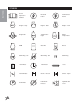
SYMBOLS Introduction 2 Read Operator’s Manual Electrical Power No Electrical Power Engine - Stop Engine - Start Engine - Run Engine Oil Temperature Light Water Temperature RPM Gasoline Diesel Glow Plug - On Glow Plug - Off Glow Plug Hour Meter Hour Meter Hand Throttle Choke - Closed Choke - Open Park Brake Park Brake Release Hydraulic Oil Level Fuse
H R Introduction SYMBOLS Up/Down Arrow Down/Lower Up/Raise No Smoking Moving Parts Manual Operation Pinch Point Step Hot Surface Hydraulic Fluid Penetration Lift Arm Tractor Engage Disengage PTO Ground Speed Fast Slow High Reverse L N Low Neutral F Forward Warning Danger Caution 3
GENERAL SAFE PRACTICES Introduction 1. It is your responsibility to read this manual and all publications associated with this machine. 2. Never allow anyone to operate or service the machine or its optional equipment without proper training and instructions. Never allow minors to operate any equipment. 3. Learn the proper use of the machine, the location and purpose of all the controls and gauges before you operate the equipment. Working with unfamiliar equipment can lead to accidents. 4.
Persons engaged in the handling, preparation or application of chemicals must follow accepted practices to insure the safety of themselves and others, 1. WEAR protective clothing including: gloves, hat, respirator, eye protection and skin covering suitable for protection from chemicals being used. 2. BATHE thoroughly after any exposure to chemicals, giving particular attention to eyes, nose, ears and mouth. 3. CLEAN equipment and materials in accordance with employer, municipal and state regulations.
SPECIFICATIONS Introduction WEIGHTS AND DIMENSIONS Length Width Height Wheel Base Weight Empty 112" (285 cm) 61" (155 cm) 50" (127 cm) 60" (152 cm) 1200 lb (544 kg) SOUND LEVEL AT 3400 RPM At ear level At 3 ft. (0.914 m) At 30 ft (9.14 m) 88 dB 84 dB 72 dB ENGINE Make Model# Type / Spec# Horsepower Fuel Cooling System Lubrication System Alternator Kohler Command CH25S PA-68666 25 hp (18.
The Model 1600H Prime Mover arrives from setup and ready for service. Depending on freight conditions the tires, wheels and steering wheel may need to be installed. The spray system is normally shipped attached to the 1600H Prime Mover. If a spray system is to be retrofitted to a 1600H Prime Mover by a dealer or owner, assemble and attach the components in accordance with the parts drawings in the Spray Star 1600H Parts/Service Manual. 1.
SET UP (CONTINUED) Introduction 10. Check brake fluid in master cylinder by removing round plug on floorboard. Add brake fluid if necessary. DOT 3. 11. Check hydraulic fluid. The hydraulic oil tank is on the right side. Fluid level should be 2 to 21/2" (5 to 6.04cm) from the top of tank when cold. 12. Machine should be greased before starting, refer to Spray Star 1600H Parts/Service Manual for location. 13.
Introduction CONTROLS & INSTRUMENTS A. Oil Light: The oil light should come on when the ignition is on, without the engine running and should go out when the engine is running. The oil light will light when the oil pressure is low. If it does come on, shut off the engine and find the cause immediately. B. Circuit Breaker: The circuit breaker is a resetable fuse. To reset push down. C. Hour/Volt Meter: The hour meter indicates the hours of machine operation.
CONTROLS & INSTRUMENTS (CONTINUED) Introduction CONTROL PANEL Located on right side of seat. The following are located on or near the control panel. A. Choke: The choke is used in starting the engine. Pull choke out to close choke plate when starting cold engine, push in when engine starts. A warm engine may not require "choking" to start. B. Hand Throttle: This hand throttle is used for hose/handgun spraying, boom spraying and sprayer calibration.
Before operating the Spray Star 1600H, become familiar with all controls and functions. Also complete all maintenance requirements and read all safety warnings. Knowing the Spray Star 1600H thoroughly, how it operates, and by doing the prescribed maintenance steps, you can expect trouble free operation for years to come. SAFETY Safety needs to always be the concern of an operator of a moving vehicle or any machine with moving parts. 1. Keep all shields and guards in place. 2.
OPERATING INSTRUCTIONS (CONTINUED) Introduction Before using the Spray Star, the operator or spray technician must familiarize themselves with all of the information on chemical spraying contained in Spraying Procedure of this manual. All testing and calibration of sprayers is to be done with water, not chemicals. This insures the safety to all involved in performing the calibration operation. Only after all calibration procedures are completed should chemical be added to the sprayer.
SPRAYER VALVE SETTINGS AND SPRAY TANK AGITATION The gate valve on the suction side of the pump, between the tank and the pump must be open before pump is engaged. Close this valve only when necessary to clean the filter with spray material in the spray tank. There is one manual flow control valves on the discharge side of the spray system. This valve controls the agitator. This valve may be opened as much as necessary to provide hydraulic agitation through the quadrajet agitator in the tank bottom.
CONSOLE FEATURES This Console (PGM F) requires selection of US (acres); SI (hectares) or TU (1,000 sq ft) area and SP1 (wheel drive, etc). A. POWER - Turns Console power OFF or ON. Turning Console OFF does not affect the data stored in the computer. B. Select manual or fully automatic control. This can automatically control two rates. C. Manual override control provides capability for spot spraying. Operation D. Booms can be controlled individually, or all at once with MASTER ON/OFF Switch E.
CONSOLE PROGRAMMING Operation When entering data into the Console computer, the entry sequence is always the same. Data must be entered into the first eight keys. 1. Depress the key which you wish to enter data. 2. Depress the “Enter” key. An “E” will illuminate in the DATA display. 3. Depress the keys corresponding to the number you wish to enter (i.e. “5”, “7”, “2”). 4. Complete the entry by again depressing the “ENTER” key. The numbers will be displayed in the DATA display as they are entered.
CONSOLE CALIBRATION (CONTINUED) 6. Recheck the new Speed Cal numbers. Zero out Distance display as in step 3. Enter the new Speed Cal number as in step 1. Repeat steps 4 and 5. MEASURE CAREFULLY. Be sure tire is properly inflated before measuring. Measure tire in type of soil in which you will be spraying. Circumference of tire will vary when measured in soft soil versus hard packed soil. For best results, measure several times and average the results. Remeasure periodically.
INITIAL PROGRAMMING OF CONSOLE COMPUTER When you first turn on Console power, after all installation procedures have been completed, the Console will flash “CAL” in the RATE display and “US” in the DATA display. This means you must “calibrate” or program the Console before it can be operated. (This is a one time operation which does not have to be repeated unless you disconnect your battery wires. Turning OFF the POWER ON/OFF switch does not affect the Console memory. All data is retained).
INITIAL PROGRAMMING OF CONSOLE COMPUTER (CONTINUED) 8. Enter SPEED CAL of 612 in key labeled: 9. Enter METER CAL calibration number in key labeled: 10. Enter VALVE CAL calibration number (2123) in key labeled: Operation 11. Enter the target RATE 1 (GPA) (lit/ha) (GPK) you want to spray in the key labeled: 12. Enter the target RATE 2 (GPA) (lit/ha) (GPK) you want to spray in the key labeled: (If you do not use a second rate, enter same rate as RATE 1 CAL).
INITIAL PROGRAMMING OF CONSOLE COMPUTER (CONTINUED) 6. To display SPEED, momentarily depress the key labeled: 7. To display VOL/MIN., momentarily depress the key labeled: This is an actual calculation of AREA/ HOUR at the present speed you are going. It is not an average over time. 9. To display TIP MONITOR fault, momentarily depress the key labeled: See TIP MONITOR manual for more detailed discussion. (Purchase the TIP MONITOR option if this function is desired.) 10.
INITIAL PROGRAMMING OF CONSOLE COMPUTER (CONTINUED) ENTER MODE SEQUENCE WITH ACTIVATED DATA-LOCK 1. Depress the key into which you wish to enter data. CODE message will appear. Enter your DATA-LOCK CODE. If code is correct, “E” will 2. Depress appear. Now enter data normally. The DATA-LOCK feature prohibits the entry of data without first entering the DATA-LOCK CODE. The DATALOCK CODE may be cleared by entering a code of “0” or by removing Console power.
INITIAL PROGRAMMING OF CONSOLE COMPUTER (CONTINUED) LOW LIMIT FLOW SET POINT AND LOW LIMIT ALARM Depress until DATA display flashes. A low limit flow rate may now be entered. CONTROL VALVE DELAY Depress until DATA display flashes. The first digit (XOOO), is the Control Valve delay digit. This feature allows the user to set a delay between the time the Booms are turned on and when the Console begins to control the flow rate. A value of 1-9 means a delay of 1-9 seconds test respectively.
CONSOLE FIELD TEST 1. Drive down field or road at target speed with sprayer booms off, to verify SPEED readout on Console. 2. Turn on sprayer and booms and place the RATE 1/RATE 2/MAN switch to RATE 1. Increase or decrease speed by one MPH (2 kph). The system should automatically correct to the target application rate. 3. If for any reason, the system is unable to correct to the desired RATE, check for an empty tank, a plugged line, a malfunctioning pump, improper vehicle speed or a defect in the system. 4.
SPRAY OPERATION (CONTINUED) TO PREVENT CORROSION After cleaning the pump as directed, flush it with a permanent type automobile antifreeze (Prestone, Zerex, etc.) containing a rust inhibitor. Use a 50% solution that is, half antifreeze and half water. Then coat the interior of the pump with a substance which will prevent corrosion such as Fluid Film or WD40. If unit will not be used for an extended period of time, disconnect hoses into and out of the pump, seal openings to the pump with caps or tape.
SPRAYING INTRODUCTION This section is intended to offer practical guidelines for the distribution of liquid chemicals over an area of turf grass such as golf courses, park land, school grounds and lawns. SMITHCO makes no representation as to the suitability of any technique or product for any particular situation. This section is suitable for self-propelled spray vehicles or sprayers mounted onto vehicles.
HOSE & HANDGUN SPRAYING A handgun (hand-nozzle or hand-lance) is used to control and direct the spray pattern to the ground, shrub or tree. They must be constructed of long lasting and noncorrosive materials such as brass, stainless or aluminum. The handgun fits to a hose of any length from the sprayer allowing operator mobility. The hose should be as short as possible while still permitting operator mobility. Liquid looses pressure due to friction as it travels through the hose, 1-3 psi (0.07-0.
NOZZLES (CONTINUED) 3. Disperse the material in a specific pattern that will insure even distribution of chemical across the swath covered by the boom. As shown (to the right) the pattern formed by flat fan (TeeJet) nozzles would show most liquid concentrated at the center, then tapering off where it begins to overlap with the next nozzle-approximately 1/3. The pattern of liquid dispersed by the hollow-cone is more even across its width. Each nozzle overlaps the adjoining nozzle by 100%.
CALIBRATION INTRODUCTION Calibrating simply means to adjust a set of variables on the sprayer in order to deliver the desired amount of chemical to a known area of turf. The job of calibrating the sprayer consists of balancing these variables so that your sprayer delivers the desired application rate. That is, an amount of chemical on a given area. It is expressed as: Gallons Per Acre (gpa) (1 US gpa = 0.83 UK gpa) or Gallons Per 1,000 Square Feet (gpt) or Liters Per Hectare (lph) (1 US gpa = 9.
THE NOZZLE CHART METHOD OF CALIBRATION The Nozzle Chart Method is useful when the sprayer nozzles are new or nearly new. It is also the most useful method to employ when the sprayer is equipped with an Electronic Spray Control System. The Electronic Spray Control System does most of the calibration work, it is up to the operator to select the proper combination of nozzle size and ground speed which will deliver the desired application rate.
THE NOZZLE CHART METHOD OF CALIBRATION (CONTINUED) 5. For Sprayer with Electronic Spray Control Systems. On sprayers equipped with Electronic Spray Control Systems such as those manufactured by Raven Ind., Micro-Trak Co. and Dickey-John Co., it is still important to select the right type and size of nozzle for the required operation. Electronic Spray Control Systems cannot function properly if the nozzles are not capable of delivering the programmed (desired) application rate.
THE “128” METHOD OF BOOM SPRAYER CALIBRATION The carrying or towing vehicle is to be traveling at the desired speed when it crosses the start line of the measured course. Repeat this procedure and determine the average of the two times. 3. With the sprayer parked, run the sprayer at the required pressure level. Catch the output of each nozzle in a container which is marked or graduated in Ounces for the exact same period of time which it took the sprayer to cover the measured course in step #2.
Nozzle Type: Spacing: Calibration: Color Size Orange XR8001 Green XR80015 DG80015 Yellow XR8002 DG8002 Blue XR8003 DG8003 Red XR8004 DG8004 Brown XR8005 DG8005 Gray XR8006 White XR8008 Steel SS8010 XR TeeJet & DG TeeJet 20 inch (51cm) US Gal/Acre (GPA) & US Gal/1,000 Square Feet (GPT) Application Nozzle Application Rate GPA Speed Pressure Capacity Speed MPH 4 5 6 7 2 3 psi (Gal/Min) 0.16 0.24 3.0 3.5 4.2 5.3 0.071 20 0.21 0.31 3.7 4.3 5.2 6.5 0.087 30 0.23 0.34 4.2 5.0 5.9 7.4 0.
NOZZLE PERFORMANCE CHART #2 Nozzle Type: Spacing: Calibration: Size Orange XR8001 Green XR80015 DG80015 Yellow XR8002 DG8002 Blue XR8003 DG8003 Red XR8004 DG8004 Brown XR8005 DG8005 Gray XR8006 White XR8008 Steel SS8010 Nozzle Charts Color 32 XR TeeJet & DG TeeJet 20 inch (51cm) Liters Per hectare Nozzle Application Rate l/ha Pressure Capacity Speed km/h 4 5 6 7 bar (l/min) 1.5 0.28 84 67.2 56.0 48.0 2.0 0.32 96 76.8 64.0 54.9 3.0 0.39 117 93.6 78.0 66.9 4.0 0.45 135 108 90.0 77.1 1.
NOZZLE PERFORMANCE CHART #3 Color Size Red TF-VS2 Brown TF-VS2.5 Gray TF-VS3 White TF-VS4 Blue TF-VS5 Green TF-VS7.5 Black TF-VS10 Turbo FloodJet 40 inch (100cm) US Gal/Acre (GPA) & US Gal/1,000 Square Feet (GPT) Nozzle Application Rate GPA Application Rate GPT Pressure Capacity Speed MPH Speed MPH 4 5 6 7 4 5 6 7 psi (Gal/Min) 20 0.28 10.4 8.3 6.9 5.9 .24 30 0.35 13.0 10.4 8.7 7.4 .30 20 0.35 13.0 10.4 8.7 7.4 .30 30 0.43 16.0 12.8 10.6 9.1 .37 20 0.42 15.6 12.5 10.4 8.9 .36 30 0.52 19.
NOZZLE PERFORMANCE CHART #4 Nozzle Type: Spacing: Calibration: Nozzle Charts 34 Color Size Red TF-VS2 Brown TF-VS2.5 Gray TF-VS3 White TF-VS4 Blue TF-VS5 Green TF-VS7.5 Black TF-VS10 Turbo FloodJet 40 inch (100cm) Liters Per Hectare Nozzle Pressure Capacity (l/min) bar 1.5 1.11 2.0 1.29 1.5 1.40 2.0 1.61 1.5 1.68 2.0 1.94 1.5 2.23 2.0 2.57 2.79 1.5 2.0 3.22 1.5 4.19 2.0 4.83 1.5 5.58 2.0 6.45 Application Rate l/ha Speed km/h 4 6 8 10 167 111 83.3 66.6 194 129 96.8 77.4 210 140 105 84.
Nozzle Type: Spacing: Calibration: Color Size Yellow 1/4 TTJ02-VS Red 1/4 TTJ04-VS Brown 1/4 TTJ05-VS Gray 1/4 TTJ06-VS White 1/4 TTJ08-VS L. Blue 1/4 TTJ10-VS L. Green 1/4 TTJ15-VS Turbo TurfJet 20 inch (51cm) US Gal/Acre (GPA) & US Gal/1,000 Square Feet (GPT) Application Rate GPT Nozzle Application Rate GPA Speed MPH (KPH) Pressure Capacity Speed MPH (KPH) 3 (5) 4 (6) 5 (8) 6 (10) 3 (5) 4 (6) 5 (8) 6 (10) psi (Gal/Min) 25 .16 15.8 11.9 9.5 7.9 .36 .27 .22 .18 30 .17 16.8 12.6 10.1 8.4 .
NOZZLE PERFORMANCE CHART #6 Nozzle Type: Spacing: Calibration: Nozzle Charts Color Size Yellow 1/4 TTJ02-VS Red 1/4 TTJ04-VS Brown 1/4 TTJ05-VS Gray 1/4 TTJ06-VS White 1/4 TTJ08-VS L. Blue 1/4 TTJ10-VS L. Green 1/4 TTJ15-VS 36 Turbo TurfJet 20 inch (51cm) Liters Per Hectare Nozzle Application Rate l/ha Pressure Capacity Speed KPH (MPH) 8 (5) 10 (6) bar (l/min) 4 (2.5) 6 (4) 1.0 0.46 69.0 46.0 34.5 27.6 1.5 0.56 84.0 56.0 42.0 33.6 2.0 0.65 97.5 65.0 48.8 32.5 3.0 0.80 120.0 80.0 60.0 48.
ABBREVIATIONS AND CONVERSIONS gpm Gallons per minute cm Centimeters lit/min Liters per minute dm Decimeters dl/min Deciliter per minute m Meter psi Pounds per square inch mm Millimeters km Kilometers mph Miles per hour gpa Gallon per acre km/h Kilometers per hour lit/ha Liters per hectare us Volume per ACRE ml/ha Milliliter per hectare Si Volume per Hectare gpk Gallons per 1,000 sq ft TU Volume per 1,000 sq ft AREA & SPEED Distance (feet) x 0.
EC Declaration of Conformity according to Directive 89/392/EEC We SMITHCO INC. (Name of supplier) 34 West Ave.
LIMITED WARRANTY SMITHCO warrants this product to be free from defects in material and workmanship under normal use for one year from the date of purchase by the original user. (60 days if product is used for rental purposes.) All warranty claims must be handled through a SMITHCO authorized dealer or by SMITHCO, INC. All transportation charges must be paid by the purchaser. There is no further express warranty.
Part #74-17 041503