PARTS & SERVICE MANUAL SWEEP STAR 48 Low Dump & High Dump Models 48-000 and 48-001 Starting Serial #: GH or GL 4983 SMITHCO PRODUCT SUPPORT 1-800-891-9435 Hwy SS and Poplar Avenue, Cameron WI 54822 E-mail: productsupport@smithco.
Introduction CONTENTS Introduction ......................................... 1-10 Service Introduction .............................................................................................. 1-3 Safe Practices ......................................................................................... 2 Specification ............................................................................................ 3 Optional Equipment ........................................................................
Thank you for purchasing a Introduction INTRODUCTION product. Read this manual and all other manuals pertaining to the Sweep Star 48 carefully as they have safety, operating, assembly and maintenance instructions. Failure to do so could result in personal injury or equipment damage. Keep manuals in a safe place after operator and maintenance personnel have read them. Right and left sides are from the operator’s seat, facing forward. All machines have a Serial Number and Model Number.
SAFE PRACTICES Introduction 1. It is your responsibility to read this manual and all publications associated with this machine (engine, accessories and attachments). 2. Never allow anyone to operate or service the machine or its attachments without proper training and instructions. Never allow minors to operate any equipment. 3. Learn the proper use of the machine, the location and purpose of all the controls and gauges before you operate the equipment.
WEIGHTS AND DIMENSIONS Length Width Height with Hopper Down Height with Hopper Up Wheel Base Weight HIGH LIFT 121" (307 cm) 60" (153 cm) 63" (160 cm) 126" (320 cm) 70" (179 cm) 1800 lbs(818 kg) SOUND LEVEL (DBA) At ear level At 3 ft (0.914 m) At 30 ft (9.
MAINTENANCE Before servicing or making adjustments to machine, stop engine and remove key from ignition. Use all procedures and parts prescribed by the manufacturer's. Read the engine manual. Service LUBRICATION Use No. 2 General Purpose Lithium Base Grease and lubricate every 100 hours. The Sweep Star 48 has eleven grease fittings. One on the top of each tower. (High Lift Only) One on the center of park brake relay on rear axle. One on hydrostatic pedal under the floorboard.
MAINTENANCE (CONTINUED) TIRE PRESSURE Caution must be used when inflating a low tire to recommended pressure. Over inflating can cause tires to explode. Front and rear tires and castor wheel should be 20 psi (1.4bar) maximum. Improper inflation will reduce tire life considerably. WHEEL MOUNTING PROCEDURE REAR WHEELS 1. Set park brake. Turn machine off and remove key. Service 2. Block one of the other wheels. 3. Loosen nuts slightly on wheel to be removed. 4.
MAINTENANCE (CONTINUED) BATTERY Batteries normally produce explosive gases which can cause personal injury. Do not allow flames, sparks or any ignited object to come near the battery. When charging or working near battery, always shield your eyes and always provide proper ventilation. Battery cable should be disconnected before using “Fast Charge”. Charge battery at 15 amps for 10 minutes or 7 amps for 30 minutes. Do not exceed the recommended charging rate.
SERVICE CHART Before servicing or making adjustments to the machine, stop engine, set park break, block wheels and remove key from ignition.
Every 500 Hours/Yearly 400 Hours 300 Hours 250 Hours 200 Hours 100 Hours Daily Service As Required END USERS SERVICE CHART § Engine Oil § Engine Oil Filter Engine for Leaks and Loose Parts ¤ Air Cleaner (Paper Element) ¤ Pre-Cleaner (Every 25 hours) ‡ Spark Plugs Idle Speed £ Air Cooling System Belts and Hoses * Tire Pressure Fuel Level Fuel Filter Hydraulic Oil **Hydraulic Oil Filter Hydraulic System for Leaks and Loose Parts Battery Electrolyte Level Clean Battery Terminals † Torque Lug Nuts Lub
ADJUSTMENTS PARK BRAKE ADJUSTMENT By turning knob on end of park brake lever you can tighten or loosen brake a small amount. To tighten turn the knob clockwise. To loosen turn counter clockwise. If this is not enough turn clevis on the rear of the brake cable to adjust length of cable. Do not adjust the clevis on the front of the machine. Service STEERING CHAIN ADJUSTMENT Steering Sprockets (A) should be level with each other. Check with straight edge. Make any adjustments.
REEL HEIGHT ADJUSTMENT Below are the various ways that the Sweep Star 48 castor wheels can be adjusted to accomodate for the finger/ brush reel height. By changing the two spacers around on the castor wheel fork you can experience a range of ground clearances on the finger/brush reel. Keep both castor wheels at the same height. These clearances change as the brush and finger reels wear.
Diagrams GROUND DUMP HYDRAULIC SCHEMATIC HIGH LIFT HYDRAULIC SCHEMATIC 11
WIRING DIAGRAM Color Code Chart Bl Br Y Grn O R B P Diagrams 12 Blue Brown Yellow Green Orange Red Black Purple
WIRING DIAGRAM PARTS LIST PART# DESCRIPTION 1 2 3 4 50-359 22-003 76-269 13-288 76-310 34-146 34-145 12-017 76-259 76-260 48-157 8892-21 22-073 48-166 48-147 14-272 8975 8977 48-144 15-314 15-472 78-368 Oil Pressure Warning Indicator Light Ammeter Power Wire to Hour Meter Key Switch with Hardware Key Set Panel Mount Circuit Breaker Circuit Breaker Boot Hour Meter Ground Wire for Hour Meter Ground Wire for Ignition Switch Ignition Module (Part of Engine) Fuel Shut-Off Solenoid (Part of Engine) Plug-In C
HYDRAULIC DIAGRAM (HIGH LIFT) Diagrams 76-023 3-Bank Hydraulic Valve Relief Valve set at 2000 PSI(137.93 Bar) 76-322 Hydrostat Pump Displacement Variable to .913 in3/R(15 cc3/R) 14.23 GPM(53.85LPM) at 3600 RPM Max Operating Speed 3600 RPM Rated Pressure 3000 PSI(206.8 Bar) Max Pressure 4500 PSI(310 Bar) Max Inlet Vacuum 5 in Hg(.17 Bar) Max Inlet Temperature 220°F(104°C) Max Allowable Case Pressure 25 PSI(1.72 Bar) 76-323 Gear Pump Displacement 14 .366 in3/R(6 cm3/R) 5.7GPM(21.
HYDRAULIC DIAGRAM PARTS LIST (HIGH LIFT) 8 9 10 11 . 12 13 14 15 16 17 18 19 20 21 22 23 24 25 26 27 28 PART# 76-242 48-012 48-013 76-321 34-057 48-015 8810-19 18-077 8895-22 18-222 48-016 8895-44 18-222 76-322 76-323 48-020 8895-40 18-222 8810-07 18-077 8895-8 18-222 8832-19 18-040 8895-22 18-222 48-083 48-083-01 48-135 48-062 8895-67 18-222 34-105 48-021 8895-92 18-222 48-018 8895-73 18-222 76-115 8895-74 18-222 76-023 48-019 8895-54.
HYDRAULIC DIAGRAM (GROUND DUMP) Diagrams 16
HYDRAULIC DIAGRAM PARTS LIST (GROUND DUMP) 1 2 3 4 5 6 7 8 9 10 11 12 PART# DESCRIPTION 42-003 8917-17 18-077 8895-20 18-222 8810-19 18-077 8895-34.5 18-222 23-006 23-031 48-135 48-060 8895-73.5 18-222 34-105 76-104 8895-20 18-222 48-016 8895-60 18-222 76-321 48-015 34-057 Hydrostatic Pump Hose 3/4 ID Hose Clamp Hose Wrap 20" Hose Clamp Hose 5/8 ID Hose Clamp Hose Wrap 34.5" Hose Clamp Oil Filter Filter Element (replacement only) Oil Tank Hydraulic Hose Hose Wrap 73.
BODY AND FRAME DRAWING (HIGH LIFT) Diagrams 18
BODY AND FRAME PARTS LIST (HIGH LIFT) 1 2 3 4 5 6 7 8 9 10 11 12 13 14 15 16 17 18 19 20 21 22 23 24 25 26 28 29 30 31 32 33 34 35 36 PART# DESCRIPTION 60-130 60-130-01 60-130-02 48-158 HB-14-20-075 HW-14 HNFL-14-20 48-161 48-173 48-159 8803-10 76-264 76-354 76-362 76-364 76-302 76-303 76-214 76-265 48-135 13-586 76-285 14-270 48-008 48-044 48-007 48-004 48-022 48-005 48-023 48-053 48-061 33-175 33-175-01 33-175-02 76-242 48-009 48-029 48-112 48-047 48-180 48-028 76-324 HB-38-16-300 HW-38 HNTL-38-16
BODY AND FRAME DIAGRAM (GROUND DUMP) Parts 20
BODY AND FRAME PARTS LIST (GROUND DUMP) 1 2 3 4 5 6 7 8 9 10 11 12 13 14 15 16 17 18 19 20 21 22 23 24 25 26 27 28 29 30 32 33 34 35 36 37 38 PART# DESCRIPTION 60-130 60-130-01 60-130-02 48-158 HB-14-20-075 HW-14 HNFL-14-20 48-173 48-161 48-159 8803-10 76-264 76-354 76-362 76-364 76-302 76-303 48-118 76-214 48-110 60-106 48-090 48-094 48-095 48-078 48-101 48-102 48-103 48-104 48-115 48-053 42-040 HNJ-34-16 48-099 48-098 48-096 48-097 33-175 33-175-01 33-175-02 48-091 48-029 48-114 48-028 76-324 48-1
STEERING DRAWING Parts 22
STEERING PARTS LIST 1 2 3 4 5 6 7 8 9 10 11 12 13 14 15 16 17 18 19 20 21 22 PART# DESCRIPTION 48-186 HWK-316-075 76-362 76-364 76-302 76-303 75-833 HSSHS-38-16-038 75-813 HWK-316-075 Steering Shaft Woodruff Key 3/16 x 3/4 Tilt Steering Mechanism Tilt Steering Boot (comes with 76-362) Steering Wheel with Cap Cap Nut 5/8 - 18 Universal Joint Socket Head Set Screw 3/8 - 16 x 3/8 Bottom Steering Shaft Woodruff Key 3/16 x 3/4 Main Frame Rubber Cap Axle Nut 11/4 - 12 Cotter Pin 1/8 x 11/2 Spacer 3/4 Seal B
FRONT FORK DRAWING Parts 24
FRONT FORK PARTS LIST 1 2 3 4 5 6 7 8 9 10 11 12 13 14 15 16 17 18 19 20 21 22 23 24 25 26 27 28 29 30 31 PART# DESCRIPTION HW-516 HB-38-16-200 HNTL-38-16 HB-38-16-250 HNTL-38-16 75-715 75-715-01 HN-38-16 HB-38-16-100 20-142 HNA-114-12 HP-18-150 20-143 20-141 HNCL-38-16 76-155 27-022-02 HNL-12-20 11-039 11-040 HB-58-18-350 HNJ-34-16 HNA-34-16 60-511 60-510 60-407 11-038 11-010 60-130 60-130-01 60-130-02 8839 60-128 60-406 HW-58 HNTL-58-18 75-676 HP-18-200 Washer 5/16 (as Req'd) Bolt 3/8 - 16 x 2 Locknu
LINKAGE DRAWING (HIGH LIFT) Parts 26
LINKAGE PARTS LIST (HIGH LIFT) 1 2 3 4 5 6 7 8 9 10 11 12 13 14 15 16 17 18 19 20 21 22 23 24 25 26 PART# DESCRIPTION HB-38-16-250 HNTL-38-16 48-026 48-163 HB-516-18-300 HW-516 HNTL-516-18 15-013 48-056 34-038 HMB-12-14 18-234 48-109 48-035 HRP-14-150 HRS-316-050 8946-1 HB-38-16-350 HW-38 HNTL- 38 -16 2 2 1 1 1 1 1 2 1 2 6 2 1 1 1 1 1 4 4 4 48-033 13-624 HRS-316-050 8946-1 HB-38-16-100 HNTL-38-16 48-034 HB-38-16-100 HW-38 HNTL-38-16 HP-18-100 48-032 HN-38-24 HMB-12-14 21-173 76-282 HN-38-24 HN
LINKAGE DRAWING (GROUND DUMP) Parts 28
LINKAGE PARTS LIST (GROUND 1 2 3 4 5 6 7 8 9 10 11 12 13 14 15 16 17 18 19 20 21 PART# DESCRIPTION HB-38-16-250 HNTL-38-16 48-026 48-163 HB-516-18-300 HW-516 HNTL-516-18 15-013 48-088 34-038 HMB-12-14 18-234 48-109 48-035 HRS-316-050 8946-1 HRP-14-150 HB-38-16-350 HW-38 HNTL- 38 -16 Bolt 3/8 - 14 x 21/2 Lock Nut 3/8 - 16 Seat Panel Filter Bracket Bolt 5/16 - 18 x 3 Washer 5/16 Lock Nut 5/16 - 18 Rubber Bumper Seat Support Centering Arm Machine Bushing 1/2 x 14GA Bushing Spring Shift Arm Rivet 3/
LINKAGE DRAWING (GROUND DUMP) CONTINUED Parts 30
REF# 22 23 24 25 26 27 28 29 30 31 32 33 34 PART# DESCRIPTION 15-015 21-173 HMB-12-14 76-282 HN-38-24 HN-38-24 HWL-38 76-299 HB-516-18-075 HW-516 HNTL-516-18 76-296 18-234 HG-14-28-180 48-059 18-234 HB-12-13-300 HNTL-12-13 76-332 75-791 10-007 HP-18-100 HSSQ-38-16-150 HN-38-16 Pedal Pad Ball Joint Machine Bushing 1/2 - 14GA Foot Pedal Rod Nut 3/8 - 24 Nut 3/8 - 24 Lock Washer 3/8 Pedal Pad Bolt 5/16 - 18 x 3/4 Washer 5/16 Lock Nut 5/16 - 18 Pedal Mount Bushing Grease Fitting 1/4 - 28 x 180° Foot Peda
CONSOLE DRAWING (HIGH LIFT) Parts 32
CONSOLE PARTS LIST (HIGH LIFT) 1 2 3 4 5 6 7 8 9 10 11 12 13 14 15 16 17 18 19 PART# DESCRIPTION 34-146 34-145 12-017 22-003 13-288 76-310 34-160 34-159 HSM-10-32-063 HSM-10-32-100 HWL-10 HN-10-32 80-020 76-214 HSA-8-075 76-309 76-023 76-224 60-106 HB-38-16-250 HW-38 HN-38-16 11-100 HP-18-100 HCP- 516-125 60-347 60-536 HB-38-16-100 HWL-38 HN-38-16 76-199 76-265 50-359 15-314 15-472 Panel Mount Circuit Breaker Circuit Breaker Boot Hour Meter Ammeter Key Switch (with hardware Kohler# 25 Key Set Throttl
CONSOLE DRAWING (GROUND DUMP) Parts 34
CONSOLE PARTS LIST (GROUND DUMP) 1 2 3 4 5 6 7 9 10 11 12 13 14 16 17 18 19 20 21 22 PART# DESCRIPTION 34-146 34-145 12-017 22-003 13-288 76-310 34-160 34-159 HSM-10-32-063 HSM-10-32-100 HWL-10 HN-10-32 80-020 76-214 HSA-8-075 76-224 60-106 HB-38-16-250 HW-38 HN-38-16 11-100 HP-18-100 HCP- 516-125 60-347 60-536 48-107 77-227 48-110 50-359 48-118 HB-38-16-400 HW-38 HNTL-38-16 15-314 15-472 Panel Mount Circuit Breaker Circuit Breaker Boot Hour Meter Ammeter Key Switch (with hardware) Key Set Throttle 48
FUEL AND OIL TANK DRAWING (HIGH LIFT) Parts 36
FUEL AND OIL TANK PARTS LIST (HIGH LIFT) 1 2 3 4 5 6 7 8 9 10 11 12 13 14 15 16 17 18 19 20 21 22 23 PART# DESCRIPTION 15-491 15-492 8832-19 18-040 18-042 15-039 13-586 HSM-8-32-050 HWS-8 48-135 17-019 18-118 76-221 23-139 18-236 HB-14-20-075 HW-14 HWL-14 8810-19 18-077 48-083 48-083-01 18-260 8810-7 18-077 18-008 18-093 18-140 18-249 48-163 HB-516-18-100 HW-516 HWL-516 Gas Tank Cap with Gauge 3 /4" Hose Clamp Reducer Bushing Fuel Valve Filler Breather Machine Screw #8 - 32 x 1/2 Star Washer #8 Oil Ta
FUEL AND OIL TANK DRAWING (GROUND DUMP) Parts 38
FUEL AND OIL TANK PARTS LIST (GROUND DUMP) 1 2 3 4 5 6 7 8 9 10 11 12 13 14 15 16 17 18 19 20 PART# DESCRIPTION 15-491 15-492 18-042 15-039 13-586 13-586-01 13-586-02 HMS-8-32-050 HWS-8 48-135 17-019 18-118 76-221 18-072 23-139 8810-19 18-077 60-213 HB-14-20-075 HW-14 HWL-14 18-145 23-006 23-031 18-008 8917-17 18-077 48-163 HB-14-20-075 HW-14 HWL-14 Gas Tank Cap with Gauge Reducer Bushing Fuel Valve Filler Breather Cap Gasket Bottom Gasket Machine Screw #8 - 32 x 1/2 Star Washer #8 Oil Tank Male Elbow
HYDRAULIC LIFT CYLINDER DRAWING Parts 40
REF# 1 2 3 PART# DESCRIPTION QUANTITY 76-242 76-242-01 18-168 76-242-02 Hydraulic Cylinder Seal Kit Elbow Clevis pin with Clip 1 1 2 2 Parts HYDRAULIC LIFT CYLINDER PARTS LIST 41
REEL LIFT CYLINDER DRAWING TAILGATE CYLINDER DRAWING Parts 42
REEL LIFT CYLINDER PARTS LIST REF# 1 2 3 4 PART# DESCRIPTION 18-168 HP-18-100 HCP-12-350 75-634 14-268 Elbow Cotter Pin 1/8 x 1 Clevis Pin 1/2 x 3 1/2 Hydraulic Cylinder Seal Kit QUANTITY 2 1 1 1 1 TAILGATE CYLINDER PARTS LIST 1 2 3 4 5 6 7 8 9 PART# DESCRIPTION HHP-18 18-168 75-714 14-268 HNJ-58-18 HNCL -58-11 18-154 HG-14-28-180 HMB-58-14 HB-58-11-200 HCP-58-175 Bridge Pin 1/8 Elbow Hydraulic Cylinder Seal Kit Jam Nut 5/8 - 18 Center Lock Nut 5/8 - 11 Rod End Grease Fitting 1/4 - 28 x 180° Machi
ENGINE AND EXHAUST DRAWING (HIGH LIFT) Parts 44
ENGINE AND EXHAUST PARTS LIST (HIGH LIFT) 1 2 3 4 5 6 7 8 9 10 11 12 13 14 15 16 17 18 19 21 22 23 24 25 PART# DESCRIPTION 48-128 48-106 23-184 18-161 23-139 23-133 76-322 HSSHS-12-13-175 HWL-12 34-163 HB-14-20-075 HNTL-14-20 76-324 76-324-03 42-113 HB-516-18-350 HW-516 HNTL-516-18 48-112 48-168 78-274 HSTP-14-20-075 48-033 23-127 48-035 8946-1 HRS-316-050 HRP-14-100 76-323 23-130 18-133 13-498 48-142 HSTP-14-20-100 HW-14 HWL-14 HN-14-20 48-180 48-143 HSTP-14-20-100 HW-14 HWL-14 HN-14-20 48-171 HB-
ENGINE AND EXHAUST DRAWING (HIGH LIFT) Parts 46
ENGINE AND EXHAUST PARTS LIST (HIGH LIFT) 26 27 28 29 30 31 32 33 PART# DESCRIPTION HB-38-16-200 HWL-38 HB-516-18-100 HNTL-516-18 78-337 HMB-100-10 48-172 HKSQ-14-150 76-340 48-169 HB-516-18-100 HNTL-516-18 34-105 48-170 HB-38-16-250 HNFL-38-16 Bolt 3/8 - 16 x 2 Lockwasher 3/8 Bolt 5/16 - 18 x 1 Lcok Nut 5/16 - 18 Electric Clutch Machine Bushing 1 x 10GA Fron t Drive Shaft Machine Key 1/4 x 1/4 x 11/2 Clutch Strap Front Cooler Bracket Botl 5/16 -18 x 1 Lock Nut 5/16 - 18 Oil Cooler Rear Cooler Bracket
ENGINE AND EXHAUST DRAWING (GROUND DUMP) Parts 48
ENGINE AND EXHAUST PARTS LIST (GROUND DUMP) 1 2 3 4 5 6 7 8 9 10 11 12 13 14 15 16 18 19 20 21 22 23 24 25 26 27 28 29 PART# DESCRIPTION 48-128 48-106 42-003 HSSHS-12-13-100 HWL-12 18-188 34-163 76-324 76-324-03 42-113 HB-516-18-350 HNTL-516-18 48-114 HSTP-14-0-075 48-168 78-274 48-033 23-130 23-139 18-161 48-035 HRP-14-100 HRS-316-050 8946-1 18-239 13-498 48-180 48-143 HSTP-14-20-100 HW-14 HWL-14 HN-14-20 48-171 HB-516-18-350 HW-516 HWL-516 HB-38-16-200 HWL-38 HB-516-18-100 HNTL-516-18 78-337 HMB-
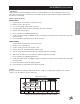
ELECTRIC CLUTCH DRIVEN BELT DRIVE DRAWING
ELECTRIC CLUTCH DRIVEN BELT DRIVE PARTS LIST REF# 1 2 3 4 5 6 7 8 9 10 11 12 13 14 15 16 17 PART# DESCRIPTION 48-038 HMB-100-10 21-445 78-337 16-013 76-217 76-298 HB-12-13-300 HW-12 HNTL-12-13 HMB-12-14 HP-18-150 76-102 76-102-01 HKSQ-14-150 76-200 HB-38-16-200 HWL-38 76-340 HB-516-18-100 HW-516 HNTL-516-18 48-169 HB-38-16-300 HW-38 HWL-38 HN-38-16 76-338 42-172 Spring Bracket Machine Bushing 1 x 10GA Spring Electric Clutch Idler Pulley Idler Arm Spacer Bolt 1/2 - 13 x 3 Washer 1/2 Lock Nut 1/2 - 13
FINGER REEL DRAWING (HIGH LIFT) Parts 52
FINGER REEL PARTS LIST (HIGH LIFT) 1 2 3 4 5 6 7 8 9 10 11 12 13 14 15 16 17 18 19 20 21 22 23 24 25 26 27 28 29 30 31 32 33 34 35 PART# DESCRIPTION HB-34-10-550 33-435 HNTL-34-10 48-046 29-585 18-223 77-171 HG-14-28-180 29-584 29-541 20-019 48-048 HCP-12-250 HHP-18 48-045 HCP-12-225 HHP-18 76-320 48-030 75-799 18-221 75-506 75-834 48-010 48-086 HB-516-18-125 HNTL-516-18 48-105 75-686 HN-38-16 HWL-38 HW-38 75-800 76-102 76-102-01 76-213 HB-12-13-350 HW-716 HNTL -12-13 76-210 48-028 75-511 HB-38-16-
FINGER REEL DRAWING (GROUND DUMP) Parts 54
FINGER REEL PARTS LIST (GROUND DUMP) 1 2 3 4 5 6 7 8 9 10 11 12 13 14 15 16 17 18 19 20 21 22 23 24 25 26 27 28 29 30 31 32 33 34 35 36 PART# DESCRIPTION HB-34-10-550 33-435 HNTL-34-10 48-046 29-585 18-223 77-171 HG-14-28-180 29-584 29-541 20-019 48-045 HCP-12-250 HHP-18 76-320 48-030 21-445 75-799 18-221 75-506 75-834 48-010 48-086 HB-516-18-125 HNTL-516-18 48-105 75-686 HN-38-16 HWL-38 HW-38 75-800 76-102 76-102-01 76-213 HB-12-13-350 HW-716 HNTL -12-13 76-210 48-028 75-511 HB-38-16-300 HB-38-16-
REAR AXLE DRAWING (HIGH LIFT) Parts 56
REAR AXLE PARTS LIST (HIGH LIFT) 1 2 3 4 5 6 7 8 9 10 11 12 13 14 15 16 17 18 19 20 21 22 23* 24* 25* 26* 27 28 29 30 31 32 33 34 35 36 37 38 39 40 41 42 43 44 * PART# DESCRIPTION 34-122 76-240 11-100 76-300 HN-516-24 21-462 60-347 60-536 48-006 48-027 48-029 8947-48 48-134 HB-38-16-125 HW-38 HNTL-38-16 13-099 HB-516-18-150 HB-12-13-400 HB-12-13-450 HW-716 HNTL-12-13 48-054 HB-58-11-250 HMB-58-14 48-043 HNTL-58-11 HB-38-16-350 HW-38 HNTL-38-16 48-042 48-055 HCP-516-100 HP-18-075 76-241 76-239 HWK-516
REAR AXLE DRAWING (GROUND DUMP) Parts 58
REAR AXLE PARTS LIST (GROUND DUMP) 1 2 3 4 5 6 7 8 9 10 11 12 13 14 15 16 17 18* 19* 20* 21* 22 23 24 25 26 27 28 29 30 31 32 33 34 35 36 * PART# DESCRIPTION 34-122 76-240 11-100 76-300 HN-516-24 21-462 60-347 60-536 48-006 48-027 48-029 48-134 HB-38-16-125 HW-38 HNTL-38-16 HB-12-13-400 HB-12-13-450 HW-716 HNTL-12-13 75-614 HB-516-18-150 48-054 48-055 HCP-516-100 HP-18-075 76-241 76-239 HWK-516-100 48-137 HB-12-13-800 HNTL-12-13 HB-12-13-750 HNTL-12-13 48-119 48-117 HN-12-13 HB-12-13-150 34-057 48-015
HOPPER AND TAILGATE DRAWING (HIGH LIFT) 48-120 48-064 48-065 Parts 60 Dust and Filtration Pack for High Lift Hopper Filter 24" x 44" Tailgate Filter 17" x 50"
HOPPER AND TAILGATE PARTS LIST (HIGH LIFT) 1 2 3 4 5 6 7 8 9 10 11 12 13 14 15 16 17 18 19 20 21 22 23 24 25 26 27 28 29 30 31 32 33 34 35 36 37 PART# DESCRIPTION 48-005 48-023 48-037 HNA-100-14 48-153 48-061 75-653 HB-38-16-250 HNW-38-16 HB-12-13-250 HMB-12-14 HNCL-12-13 48-053 HB-38-16-125 HNTL-38-16 48-025 HB-34-10-500 HNTL-34-10 13-099 HB-516-18-125 HWL-516 48-022 48-004 48-044 48-131 76-159 HDSPS-14-075 76-242 76-242-02 48-007 HNA-114-12 HB-58-11-300 HNTL-58-11 48-041 HB-58-11-200 HMB-58-14 H
HOPPER AND TAILGATE DRAWING (GROUND DUMP) Parts 62
HOPPER AND TAILGATE PARTS LIST (GROUND DUMP) 1 2* 3 4 5 6 7 8* 9 10 11 12 13 14 15 16 17 18 19 20 21 22 23 24 25 * PART# DESCRIPTION 48-104 48-063 48-115 HB-14-20-075 HNTL-14-20 48-103 42-040 HNJ-34-10 HB-12-13-200 HNCL-12-13 HMB-12-14 48-097 48-122 48-102 48-091 HB-38-16-125 HW-38 HNTL-38-16 48-094 48-078 48-090 76-151 HCP-34-175 HHP-18 HB-34-10-400 HMB-34-10 HNTL-34-10 48-116 26-034 HWL-516 HN-516-18 HB-12-13-200 HMB-12-14 HNTL-12-13 48-096 48-098 48-099 10-025 HB-12-13-150 HMB-12-14 HNTL-12-1
76-322 15 SERIES SUNDSTRAND PUMP DRAWING (HIGH LIFT) NOTE: #8 is Gage Port Parts 64
76-322 15 SERIES SUNDSTRAND PUMP PARTS LIST (HIGH LIFT) 1 2 3 4 5 6 8 9 10* 11 12 13 14A 15*A 16A 17A 18A 19B 20B 21*B 22B 24B 25*B 29* 30 31 32 33 34 35 36 37 38 39 40* 41 42* 43 48 49 50 51† 52 53 54 * † A B PART# DESCRIPTION 42-003-01 14-130 13-110-01 14-115 42-003-16 76-322-02 13-110-05 14-069 42-003-04 42-003-05 14-212 14-105 13-110-10 QUANTITY O-Ring Ring By-Pass Valve Valve Plate Cylinder Block Kit Pump Shaft Pipe Plug Needle Bearing Lip Seal Washer Truncated Shaft (short 1 holes) Retaining Rin
42-003 HYDROSTATIC PUMP DRAWING (GROUND DUMP) NOTE: #8 is Gage Port Parts 66
42-003 HYDROSTATIC PUMP PARTS LIST (GROUND DUMP) 1* 2 3 4 5 6 7 8 9 10* 11 12 13 14A 15*A 16A 17A 18A 19C 20C 21*C 22C 24C 25*C 26B 27B 28B 29*B 30B 31 32 33 34 35 36 37 38 39 40* 41 42* 43 44D 45D 46*D 47D 48 49 50 * A B C D PART# DESCRIPTION 42-003-01 14-130 13-110-01 14-115 42-003-16 42-003-02 42-003-03 13-110-05 14-069 14-014 42-003-05 14-220 14-105 13-110-10 13-110-07 42-003-12 42-003-13 42-003-17 O-Ring Ring By-Pass Valve Valve Plate Cylinder Block Kit Pump Shaft Plug Pipe Plug Needle Bearing Li
48-137 REAR WHEEL MOTOR (10.3 C.I.
48-137 REAR WHEEL MOTOR (10.3 C.I.
76-023 3 -BANK HYDRAULIC VALVE DRAWING Parts 70
76-023 3 -BANK HYDRAULIC VALVE PARTS LIST 1 2 3 4 6 7 8 9 10 11* 13* 14 15 16 17* 18* 19 20 21 22 23 * PART# DESCRIPTION 76-023-03 HN-516-18 HW-14 76-023-06 18-168 18-202 76-023-01 76-023-02 76-023-09 76-023-10 Mounting Bracket Hex Nut 5/16 - 18 Washer 1/4 Tie Rod Elbow 90° Elbow 90° Linkage (comes with handle) Valve Handle (sold as a set of 3) Body and Spool (matching set) In-body O-Ring O-Ring Inlet Kit (load check and relief, 2000 psi) Inlet with Load Check Adapter Mylar Shim O-Ring Spring (type 10
NOTES 72
DECAL LIST This is a list of decals on the Sweep Star 48. Part number, description, and location will help in reordering decals.
QUICK REFERENCE REPLACEMENT PARTS REPLACEMENT FILTERS 23-031 48-083-01 78-090 76-324-01 76-324-02 50-403 Hydraulic Oil Filter (Ground Dump) Hydraulic Oil Filter (High Dump) Oil Filter Air Element Pre-Cleaner Fuel Filter for Kohler REPLACEMENT BELTS 76-200 Finger Reel Belt 2/A74 SEAL KITS 76-023 14-096 3-Bank Hydraulic Valve O-Ring Seal Kit 76-322 42-003 14-098 Hydrostatic Pump (High Lift) Hydrostatic Pump (Ground Dump) Seal Kit 76-323 Gear Pump (non-repairable) 48-137 14-080 Wheel Motor Seal Kit
LIMITED WARRANTY SMITHCO warrants this product to be free from defects in material and workmanship under normal use for one year from the date of purchase by the original user. (60 days if product is used for rental purposes.) All warranty claims must be handled through a SMITHCO authorized dealer or by SMITHCO, INC. All transportation charges must be paid by the purchaser. There is no further express warranty.