Use & Care Guide Outdoor Gas Smoker Model Number: GS-9933 NOTICE TO INSTALLER: LEAVE THESE INSTRUCTIONS WITH THE GRILL OWNER FOR FUTURE REFERENCE. NOTICE TO CONSUMER: RETAIN THIS OWNER’S MANUAL FOR FUTURE REFERENCE.
DANGER TABLE OF CONTENTS Important Safety Warnings . . . . . . . . . . . . . . . . . . . . . . . . . . 2–4 Product Features. . . . . . . . . . . . . . . . . . . . . . . . . . . . . . . . . . . . 4 Carton Contents . . . . . . . . . . . . . . . . . . . . . . . . . . . . . . . . . . 4–6 Assembly Instructions . . . . . . . . . . . . . . . . . . . . . . . . . . . . . 7–13 Connecting the LP Tank . . . . . . . . . . . . . . . . . . . . . . . . . . . 14–15 If you 1. 2. 3. 4.
IMPORTANT SAFETY WARNINGS WE WANT YOU TO ASSEMBLE AND USE YOUR SMOKER AS SAFELY AS POSSIBLE. THE PURPOSE OF THIS SAFETY ALERT SYMBOL IS TO ATTRACT YOUR ATTENTION TO POSSIBLE HAZARDS AS YOU ASSEMBLE AND USE YOUR SMOKER. WHEN YOU SEE THE SAFETY ALERT SYMBOL PAY CLOSE ATTENTION TO THE INFORMATION WHICH FOLLOWS! READ ALL SAFETY WARNINGS AND INSTRUCTIONS CAREFULLY BEFORE ASSEMBLING AND OPERATING YOUR SMOKER.
WARNING • An LP cylinder not connected for use should not be stored in the vicinity of the smoker or any other appliance. DO NOT store spare LP cylinders within 10 feet of the smoker. LP cylinders must be stored outdoors, out of reach of children. DO NOT store LP cylinders in a building, garage, or any other enclosed area. PRODUCT FEATURES Appliance style magnetic closure Four adjustable chrome plated steel cooking grills • DO NOT store LP gas cylinders inside or on top of the smoker.
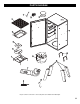
PARTS DIAGRAM 1 3 2 4 5 6 7 8 11 10 9 13 12 15 14 Inspect contents of the box to ensure all parts are included and undamaged.
HARDWARE BAG CONTENTS QUANTITY 2 Heat Resistant Washers (Door Handle) 7 M5 X 16 mm Bolts 15 M6 X 16 mm Bolts 2 M4 X 25 mm Bolts 3 M5 mm Nuts 3 #10 Washers 7 Gaskets (2) (7) M5 X 16 mm Bolts (15) M6 X 16 mm Bolts (2) M4 X 25 mm Bolts (3) (3) #10 Washers (7) 6 Heat Resistant Washers (Door Handle) M5 mm Nuts Gaskets
ASSEMBLY Choose a level, cleared assembly area and get a friend to help you put your smoker together. Lay cardboard down to protect smoker finish and assembly area. Leg with Hole CAUTION: Some parts may contain sharp edges. Wear protective gloves if necessary. Note: With the help of a friend, turn the smoker cabinet upside down. Bolt Holes Step 1 Line up holes of leg and cabinet, and attach with M6 X 16 mm bolts; nuts are pre-welded to cabinet. Securely tighten bolts.
Step 4 Set the burner assembly onto the cabinet as shown. Burner Tube Gas Valve Orifice CAUTION: Make sure the valve gas orifice slides and fits into the burner tube. #10 Washers Gaskets Step 5 Secure the burner assembly with the three M6 X 16 mm bolts with #10 washers and gaskets from the inside of the cabinet. Securely tighten the bolts. Burner Tube Step 6 Attach the loose igniter wire to the igniter on the control panel as shown.
Step 7 Set the smoke stack on top of the cabinet and line it up with the matching holes. Insert three M5 X 16 mm bolts through smoke stack base and into cabinet. Secure with three M5 mm nuts. Step 8 Line up the side handle with the matching holes on each side of the cabinet as shown. The handles must be positioned upright with the bolt holes on the bottom as shown. Insert two M5 X 16 mm bolts and gaskets from the outside and thread into the holes in the side of the cabinet as illustrated. Tighten securely.
Step 11 Insert all cooking grills into rack supports respectively as shown. Make sure each cooking grill is firm and level. Step 12 Slide the water pan into the bottom rack position as shown. Make sure water pan is firm and level.
Step 13 Mount the door handle with two M4 X 25 mm bolts and two heat resistant washers. Insert each bolt through the door from the inside. From the outside place a heat resistant washer over each bolt. Then thread the bolts into the handle. Tighten each bolt securely. Heat Resistant Washers Step 14 Insert the temperature gauge with bezel through the mounting hole in the front of the door. Place a wing nut onto the temperature gauge stem from the inside of the door panel and tighten it firmly.
Step 15 Place one end of the S-Hook through the hole on the side of the regulator as shown. Step 16 When an LP tank is not attached to the smoker, use the S-Hook to hang the hose/regulator from the carry handle on the side of the smoker. This will help prevent dirt and other particles from plugging the end of the assembly. Step 17 Using a zip tie, secure the hose to the front leg as shown. Do not pull the zip tie tight, leave it just loose enough so that the hose can be adjusted if needed.
Gas Smoker Assembled 13
CONNECTING THE LP TANK WARNING WARNING • Do not store tanks under or near the smoker. • Never fill tanks more than 80% full. ALL INSTRUCTIONS AND SAFEGUARDS ON THIS PAGE MUST BE FOLLOWED TO PREVENT FIRE, DAMAGE, AND/OR INJURY. 1. The knob on the LP tank must be closed. See that the knob is turned clockwise to a full stop. 2. Check that control knob on the smoker is turned off. 3. Remove the protective cap from the LP tank valve and coupling nut, if present. 4.
The regulator/hose assembly should be handled carefully to prevent contamination by foreign objects and dirt. Clean and inspect the hose before each use of the appliance. If there is evidence of abrasion, wear, cuts or leaks, the hose must be replaced prior to the appliance being put into operation. In order to insure proper operation, any replacement of the fuel tank regulator must be done with identical replacement parts. This unit is not to be utilized with a non-self-contained LPgas supply system.
ADDING WOOD/CHARCOAL To add wood chips before cooking, simply fill the wood chip box with your choice of flavoring hardwood chips. The amount and type of wood you use is entirely up to you. One full box is typically enough for several hours of smoking. Once the box is filled, place the lid on top of the box and set the box in the smoker.
MATCH LIGHTING: 1. Repeat steps 1 thru 5 of the Igniter Lighting System above. 2. Remove the Wood Chip Box and its stand from inside the smoker. Light a paper match and drop it into the burn chamber, making sure it falls next to the brass burner. Quickly turn the control knob to the high setting. If the burner does not light within 5 seconds, turn the control knob off, wait 5 minutes for gas to clear, and repeat the process.
TEMPERATURE CHART AFTER USE SAFETY AND MAINTENANCE WARNING: To ensure that it is safe to eat, food must be cooked to the minimum internal temperatures listed in the table below. USDA* Safe Minimum Internal Temperatures Fish . . . . . . . . . . . . . . . . . . . . . . . . . . . . 145º F Pork. . . . . . . . . . . . . . . . . . . . . . . . . . . . 160º F Egg Dishes . . . . . . . . . . . . . . . . . . . . . . 160º F Steaks and Roasts of Beef, Veal or Lamb . . . . . . . . . . . . .
• If your temperature gauge seems to be out of calibration: Remove the heat indicator from the door of the smoker by loosening and removing the mounting nut from the inside. There is a second nut mounted on the back of the heat indicator that can be turned to adjust the heat indicator needle. Set the needle to the current outdoor ambient temperature and re-mount the heat indicator to the door of the smoker. • To clean the inside and outside of the smoker cabinet, simply use a damp cloth.
Manual de uso y cuidado SMOKEHOUSE Ahumador a Gas para uso al Aire Libre Numero de Modelo: GS-9933 AVISO PARA EL INSTALADOR: ENTREGUE ESTAS INSTRUCCIONES AL PROPIETARIO DE LA PARRILLA PARA REFERENCIA FUTURA. AVISO PARA EL PROPIETARIO: GUARDE ESTAS INSTRUCCIONES DE LA PARRILLA PARA REFERENCIA FUTURA.
PELIGRO TABLA DE CONTENIDO Importantes Advertencias de Seguridad. . . . . . . . . . . . . . 21–23 Características del Producto. . . . . . . . . . . . . . . . . . . . . . . . . . 23 Contenido del Cartón . . . . . . . . . . . . . . . . . . . . . . . . . . . . 23–25 Instrucciones de Asamblaje . . . . . . . . . . . . . . . . . . . . . . . 26–33 Conexión de Cilindro de Propano Líquido (LP) . . . . . . . . . 34–35 Instrucciones de Operación . . . . . . . . . . . . . . . . . . . . . . .
ADVERTENCIAS IMPORTANTES DE SEGURIDAD ADVERTENCIA ahumador en un lugar seco y protegido. ES NUESTRO DESEO QUE ARME Y UTILICE SU PARRILLA EN LA FORMA MÁS SEGURA POSIBLE. EL PROPÓSITO DE ESTE SÍMBOLO DE ALERTA DE SEGURIDAD ES QUE USTED PRESTE ATENCIÓN A LOS POSIBLES PELIGROS CUANDO ARME Y UTILICE SU PARRILLA.
ADVERTENCIA • Un cilindro de gas LP no conectado para uso no se debe almacenar en la vecindad del ahumador o otro aparato. No almacene los cilindros de gas LP menos de 10 pies del ahumador. Los cilindros de gas LP se deben almacenar al aire libre, fuera del alcance de niños. No almacene los cilindros de gas LP en un edificio, garaje, o ninguna otra área encerrada. • No almacene cilindros de gas LP dentro o encima del ahumador.
DIAGRAMA DE PIEZAS PARA MODELO 125.15884801 1 3 2 4 5 6 7 8 11 10 9 13 12 15 14 Inspeccione el contenido de la caja para cerciorarse de que tenga todas las piezas intactas.
CONTENIDO DE BOLSA DE FERRETERÍA CANTIDAD 2 Arandelas Resistentes al Calor (Asidero de Puerta) 7 M5 X 16 mm Pernos 15 M6 X 16 mm Pernos 2 M4 X 25 mm Pernos 3 M5 mm Reborde 3 #10 Arandelas 7 Juntas (2) Arandelas Resistentes a Calor (Asidero de Puerta) (7) M5 X 16 mm Pernos (15) M6 X 16 mm Pernos (2) M4 X 25 mm Pernos (3) (3) #10 Arandelas (7) M5 mm Reborde Juntas 25
ENSAMBLAJE Seleccione una zona nivel y despejada y pídale a un amigo a que le ayude a ensamblar su ahumador. Ponga cartón debajo para proteger el acabado del ahumador y la zona del ensamblaje. PRECAUCIÓN: Algunas piezas pueden tener bordes filosos. En caso necesario, póngase guantes de protección. Pierna con Agujero Nota: Con la ayuda de un amigo, voltee el gabinete del ahumador al revés.
Tubo del Quemador Paso 4 Coloque el ensamblaje de la hornilla sobre el gabinete como se muestra. Orificio de la Válvula de Gas PRECAUCIÓN: Cerciórese de que el orificio del gas de la válvula resbale y los ajustes dentro del tubo de la hornilla. #10 Arandelas Juntas Paso 5 Fije el ensamblaje del quemador con los tres pernos M6 X 16 mm con #10 arandelas y juntas desde el interior del gabinete. Apriete bien los pernos.
Paso 7 Coloque la chimenea sobre la parte superior del gabinete y alinéela con los orificios correspondientes. Inserte tres pernos de M5 X 16 mm al gabinete, a través de la base de la chimenea. Fíjelos con tres tuercas de reborde de M5 mm. Paso 8 Alinee la manija lateral con los orificios correspondientes ubicados lateralmente en cada lado del gabinete como se indica. Las manijas deben ir colocadas en posición vertical con los orificios para los pernos en la parte inferior como se muestra.
Paso 9 Inserte la estante de la caja para pedazo de madera a la parte inferior del ahumador. Las piernas de la rejilla se asientan en las cuatro marcas de la parte inferior. Paso 10 Coloque la caja para astillas de madera en la rejilla. Asegúrese de que esté bien asentada y fija en el centro de la rejilla. Coloque la cubierta sobre la caja para astillas de madera. Paso 11 Inserte todas las rejillas para cocinar en los respectivos soportes de las rejillas como se muestra.
Paso 12 Deslice la bandeja de agua a la parte inferior de la rejilla como se muestra. Asegúrese de que la bandeja de agua esté firme y nivelada. Paso 13 Monte la manija de la puerta con dos pernos M4 X 25 mm y dos arandelas resistentes al calor. Inserte cada perno a través de la puerta desde el interior. Desde el exterior, coloque una arandela resistente al calor sobre cada perno, luego enrosque los pernos a la manija. Apriete bien cada perno.
Paso 14 Inserte el indicador biselado de temperatura a través del agujero de montaje en el frente de la puerta. Coloque la tuerca ala al vástago del indicador de temperatura desde el interior del panel de la puerta y apriete bien. Paso 15 Coloque un extremo del Gancho S a través del agujero en el lado del regulador como se muestra. Paso 16 Cuando un tanque de gas LP no esté unido al ahumador, use el gancho en “S” para colgar la manguera o el regulador de la agarradera ubicada a lado del ahumador.
Paso 17 Con una abrazadera, fije la manguera a la pata frontal como se muestra. No jale la abrazadera para apretarla, déjela sólo lo suficientemente floja para que la manguera puede ajustarse en caso necesario. Si amarra la manguera a la pata evitará que la manguera toque la cámara caliente del quemador. Revise la instalación debajo del ahumador para asegurarse de que la manguera no esté rozando alguna parte de la cámara del quemador.
Ensamblaje del ahumador a Gas 33
CONECTANDO EL TANQUE DE GAS LP ADVERTENCIA • No almacene tanques bajo o cerca del ahumador. • Nunca llene tanques más del 80%. ADVERTENCIA DEBEN SEGUIRSE TODAS LAS INSTRUCCIONES Y PRECAUCIONES DE ESTA PÁGINA PARA EVITAR DAÑOS, INCENDIOS O LESIONES. 1. Debe cerrarse la perilla del tanque de gas LP. Fíjese que la perilla haya sido girada hasta el tope en el sentido de las manecillas del reloj. 2. Revise que la perilla de control del ahumador haya sido apagada. 3.
El montaje del regulador/manguera se debe manejar cuidadosamente para prevenir la contaminación por los objetos extranjeros y la suciedad. Limpie y examine la manguera antes de cada uso. Si hay evidencia de la abrasión, use, los cortes o los escapes, la manguera se debe substituir antes de que el aparato se ponga en uso. Para asegurar la operación apropiada, cualquier reemplazo del regulador del depósito de gasolina se debe hacer con las piezas de reemplazo idénticas.
CÓMO AGREGAR LEÑA O CARBÓN Para agregar las astillas de madera antes del cocimiento, simplemente llene la caja para astillas de madera con sus pedacitos de leña favoritos para darle sabor. Use la cantidad y el tipo de leña que desee. Una caja llena es generalmente suficiente para varias horas de ahumado. Una vez que la caja esté llena, coloque la cubierta encima de la caja y póngala en el ahumador.
CÓMO ENCENDER CON UN FÓSFORO: 1. Repita los pasos 1 a 5 del "Sistema de Encendido del Encendedor" arriba. 2. Retire la caja para astillas de madera y su soporte del interior del ahumador. Encienda un papel con el fósforo y déjelo caer en la cámara del quemador, asegurándose que caiga junto al quemador de latón. Dé vuelta rápidamente a la perilla de control a alto.
TABLA DE TEMPERATURA SEGURIDAD Y MANTENIMIENTO DESPUÉS DEL USO ADVERTENCIA: Para asegurarse de que sea seguro comer, el alimento se debe cocinar a las temperaturas internas mínimas enumeradas en la tabla abajo. Temperaturas Internas Mínimas Seguras de USDA* Pescado . . . . . . . . . . . . . . . . . . . . . . . . 145º F Cerdo . . . . . . . . . . . . . . . . . . . . . . . . . . 160º F Platillos de Huevo . . . . . . . . . . . . . . . . 160º F Filetes y Carnes Asadas, de Ternera o de Cordero. . . . . . . . .
• Si su indicador de calor parece ya no estar bien calibrado, retírelo de la puerta del ahumador aflojando y quitando la tuerca de montaje desde el interior. Hay una segunda tuerca montada en la parte trasera del indicador de calor que puede girarse para ajustar la aguja del indicador. Fije la aguja a la temperatura ambiente externa actual y vuelva a montar el indicador de calor a la puerta del ahumador. • Limpie el interior y exterior de la puerta del gabinete del ahumador sólo con un trapo o paño húmedo.