OWNER’S MANUAL CE-8.
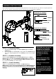
SAFETY INSTRUCTIONS WARNING: To reduce the risk of serious injury, read the following Safety Instructions before using the Elliptical Trainer. 1. Read all warnings posted on the Elliptical Trainer. 2. Read this Owner's Manual and follow it carefully before using the Elliptical Trainer. Make sure that it is properly assembled and tightened before use. 3. We recommend that two people be available for assembly of this product. 4. Keep children away from the Elliptical Trainer.
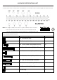
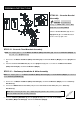
HARDWEAR IDENTIFICATION CHART This chart is provided to help identify the hardware used in the assembly process. Place the washers, the end of the bolts, or screws on the circles to check for the correct diameter. Use the small scale to check the length of the bolts and screws. NOTE: The length of all bolts and screws except those with flat heads is measured from below the head to the end of the bolt or screw. Flat head bolts and screws are measured from the top of the head to the end of the bolt or screw.
“BEFORE YOU BEGIN” Too often, our busy lifestyles limit our time and Thank you for choosing the CE-8.0LC Elliptical. We take great pride in producing this quality product and hope it will opportunity to exercise. The equipment provides a provide many hours of quality exercise to make you feel convenient and simple method to begin your assault on better, look better and enjoy life to its fullest. getting your body in shape and achieving a happier and healthier lifestyle.
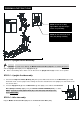
“ASSEMBLY INSTRUCTIONS” Place all parts from the box in a cleared area and position them on the floor in front of you. Remove all packing mat erials from your area and place them back into the box. Read each step carefully before beginning. Detailed Lever- drawing 1 Stabilizer Adjustment Plate Leveler (58) Detailed Lever- drawing 2 Stabilizer Adjustment Plate Screw line Leveler (58) LEVELING: After placing the STEP 1 – Leveler Assembly a. b.
“ASSEMBLY INSTRUCTIONS” NOTE: Please do not fully tighten Bolts (95) until Step. 8 for the easy assembly NOTE: Do not remove the lock nuts (103) during assembly STEP 4 – Upright Sleeve Assembly CAUTION: Be careful not to damage the Middle Connection Wire (109) while assembling Step 4 to 6. Slide the Upright Sleeve (22) onto the Upright Post (4). Refer to the drawing above. Make sure the direction of the Upright Sleeve (22) is in the correct position. STEP 5 – Upright Post Assembly a.
“ASSEMBLY INSTRUCTIONS” STEP 7 – Pedal Support Arm & Pivoting Arm Assembly a. Attach the Left Pedal Support Arm (10) onto the Left Pivoting Arm (8) and secure with the 1x Button Head Bolt (M10xp1.5x85mm) (90) and 1 x Nylon lock Nut (M10xp1.5) (104). b. Press the Nut Cap (105) onto the Nylon lock Nut (M10xp1.5) (104). c. Repeat the above procedure to attach the Right Pedal Support Arm (11) onto the Right Pivoting Arm (9).
“ASSEMBLY INSTRUCTIONS” STEP 9 – Pedal Assembly a. Attach the Left Pedal Assembly (33L) onto the pedal arm plate that is located in the middle of the Left Pedal Support Arm (10) and secure with the 4x Socket Head Bolt (M8xp1.25x10mm) (83). b. Repeat the above procedure to attach the Right Pedal Assembly (33R) onto the Right Pedal Support Arm (11).
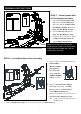
“ASSEMBLY INSTRUCTIONS” STEP 10 – Console Bracket Assembly CAUTION: Be careful not to damage the Middle Pulse Sensor Wire (112) while assembling STEP 9. Slide the Console Bracket (18) onto the Upright Post (4) as the FIG1 illustration shows on the top right corner. STEP 11– Console Fixed Bracket Assembly NOTE: For shipping purpose, the 4 x Button Head Bolts (M8xp1.25x12mm) (87) and 4 x Lock Washers (M8)(66) are attached on the Upright Post (4). a. Remove the 4 x Button Head Bolts (M8xp1.
“ASSEMBLY INSTRUCTIONS” STEP 13 – Wire Assembly a. Connect the Upper Pulse Sensor Wire (111) to the Middle Pulse Sensor Wire (112). b. Connect the Upper Connection Wire (108) to the Middle Connection Wire (109). NOTE: The number of wire pin should be the same for both wires to connect with as the drawing shown on the right. STEP 14 – Console & Console Bracket Assembly a. b. c. Place the Console (17) onto the Upright Post (4) and secure wit h the Round Head Screws (M5xp0.8x15mm) (80).
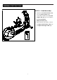
“ASSEMBLY INSTRUCTIONS” STEP 16 – Upper Handlebar Assembly NOTE: For shipping purpose, the Button Head Bolts (M8xp1.25x16mm)(88) and Lock Washers (M8)(66) are attached on the Left and Right Action Handlebar (6, 7). a. Remove the 8x Button Head Bolts (M8xp1.25x16mm) (88) and 8 x Lock Washers (M8) (66) from the Left and Right Action Handlebar (6, 7). b. Following the assembly drawing, insert the Right Action Handlebar (7) onto the Right Pivoting Arm (9) and secure with the 4x Button Head Bolts (M8xp1.
“OPERATION INSTRUCTIONS” A. POWER SUPPLY The power connects to the front of the Main Frame (1.) Plug the adaptor’s Power Cord (106B) into an 110v electrical outlet. B. CONSOLE ANGLE ADJUSTMENT A To get the best viewable angle, press the area A or B to adjust the display up or down. B C. HOW TO MOVE THE ELLIPTICAL Move this elliptical by lifting from the front stabilizer and roll the elliptical on the wheels located on the rear stabilizer. This elliptical may reqire two people to move.
COMPUTER OPERATION Congratulations this product is equipped with the MY SMOOTH Virtual Fitness Trainer. Whether you want to lose weight, train for a sporting event, or simply maintain a healthy lifestyle, the MY SMOOTH Virtual Fitness Trainer provides the tools, structure and support you need to be fit and live healthy. The 5 simple steps, outlined in the customer care kit* are proven to help you lose weight, improve your health, and make positive steps to a healthier lifestyle.
COMPUTER OPERATION Speaker Take a few minutes to review the console layout. Below is an overview of the console’s features and functions We recommend that you use the cons ole to help vary your work out routine and keep you focused on your process toward your fitness goals. The console can become an important source of motivation and interest which will help keep you on track Power ON a. b.
COMPUTER OPERATION Console Buttons a. Press START/PAUSE to begin your exercise b. Press START/PAUSE again to stop and pause all functions during your exercise program. All the data on the display will then pause. c. Press START/PAUSE again to resume the program and all the data displayed will continue until the program has finished. d. HOLD TO RESET function: Press and hold START/PAUSE, all the data will return to 0 and the console will return to POWER ON status.
COMPUTER OPERATION Console Buttons Speaker Sound System: a. To use the music feature, simply connect any MP3/CD play er to the LI NE IN jack on the console. b. Listen to the music, either through headphones or speakers. c. Use the “Volume Knob” to adjust the sound level. To record your exercise and health metrics, you must log on to www.mysmoothtrainer.com . Then sync your MY Smooth Virtual Fitness Trainer USB device.
COMPUTER OPERATION Console Functions CALORIES: Count Up: Measuring total calories your body burned during exercise. Display range: 0 ~ 9999. SPEED: Displays the current speed KM/MILE during exercise. RPM (Rotation Per Minute): Display range: 0 ~ 999. TIME: Count Up: If a target time was not selected, TIME will count up from 0:00 to maximum 99:59 minutes.
COMPUTER OPERATION GENDER: Display range: Male: Female: AGE: Display range: 10 ~ 99 years old; in 1 year increments NOTE: Although the console allows input for age beginning at 10 years old, the product is not recommended for use by children. HEIGHT: Display range: 3 FEET 4 INCHES ~ 7 FEET; 1 INCH increments / 101 ~ 214 CM; 1 CM increments; the product is not recommended for use by children.
COMPUTER OPERATION “1” Press any button on the console to turn on the console a. Make sure that the power cord is properly plugged into the socket. b. The console would automatically shut off after 5 minutes of inactivity. c. Press any button on the console to turn on the console. A fter a few seconds, the console will then light up with a short beep sound, indicating the console will be ready for use.
COMPUTER OPERATION “B. SET YOUR GENDER“ a. After pressing UP or Down button to enter into MANUAL function mode will appear with PROGRAM press ENTER to Confirm, the GENDER /Male icon display flashing. b. Use UP or DOWN buttons to set your gender (Male: or Female: ). c. Press the ENTER button to confirm. “C. SET YOUR AGE“ a. The AGE function will appear with the AGE display flashing. b. Use the UP or DOWN buttons to set your AGE (10 ~ 99 YEARS OLD; in 1 YEAR INCREMENTS). c.
COMPUTER OPERATION “F. SET THE TIME“ a. The TIME function will appear with the TIME display flashing. b. Use the UP or DOWN buttons to set the desired TIME (00:00 TO 99:00; 1 MINUTE INCREMENTS). c. Press the ENTER button to confirm. NOTE for TIME: Count Up: If a target time was not selected, the TIME will count up from 0:00 to a maximum of 99:59 minutes Count Down: If you have set the target time, the console will count down from that selected target time to 0:00 “G.
COMPUTER OPERATION “CONSOLE INSTRUCTIONS – PROGRAM (P2 ~ P10)” “A.“ENTER THE PRESET PROGRAMS” To enter one of the nine preset programs. a. Press any button on the console to turn on the console. Aft er a few seconds, the console will then light up with a b. c. d. e. f. short beep sound, indicating the console will be ready for use. Make sure that the power cord is properly plugged into the socket. The console would automatically shut off after 5 minutes of inactivity.
COMPUTER OPERATION “D. SET YOUR HEIGHT“ a. The HEIGHT function will appear with the HEIGHT display flashing. b. Use the UP or DOWN buttons to set your HEIGHT (3 FEET 4 INCHES ~ 7 FEET; 1 INCH INCREMENTS/ 101 ~ 214 CM; 1 CM c. INCREMENTS). Press the ENTER button to confirm. NOTE for HEIGHT: The product is not recommended for use by children “E. SET YOUR WEIGHT“ a. The WEIGHT function will appear with the WEIGHT display flashing. b.
COMPUTER OPERATION “G. START TO EXERCISE” Press START/ PAUSE to begin your exercise. “H.
COMPUTER OPERATION P1 WEIGHT LOSS P2 NOVICE INTERVAL P3 INTERMEDIATE INTERVAL P4 MOUNTAIN CLIMB P5 HILL CLIMB P6 ROLLING HILLS P7 GRADUATING INTERVAL P8 PLATEAU P9 ADVANCED INTERVAL P10 LADDER 25
COMPUTER OPERATION “CONSOLE INSTRUCTIONS – PROGRAM (P11 ~ 12)” P11 USER 1 P12 USER 2 “1” To enter one of the 2 USER programs. a. Press any button on the console to turn on the console. A fter a few seconds, the console will then light up with a b. c. d. e. f. short beep sound, indicating the console will be ready for use. Make sure that the power cord is properly plugged into the socket. The console would automatically shut off after 5 minutes of inactivity.
COMPUTER OPERATION ” C. SET YOUR AGE” a. The AGE function will appear with the AGE display flashing. b. Use the UP or DOWN buttons to set your AGE (10 ~ 99 YEARS OLD; in 1 YEAR INCREMENTS). c. Press the ENTER button to confirm .NOTE: Although the console allows input for age beginning at 10 years old, the product is not recommended for use by children “D. SET YOUR HEIGHT“ a. The HEIGHT function will appear with the HEIGHT display flashing. b.
COMPUTER OPERATION “F. SET THE TIME“ a. The TIME function will appear with the TIME display flashing. b. Use the UP or DOWN buttons to set the desired TIME (00:00 TO 99:00; 1 MINUTE INCREMENTS). c. Press the ENTER button to confirm. NOTE for TIME: Count Up: If a target time was not selected, the TIME will count up from 0:00 to a maximum of 99:59 minutes Count Down: If you have set the target time, the console will count down from that selected target time to 0:00 ”G.
COMPUTER OPERATION “1” Prior information: Press any button on the console to turn on the console a. b. c. Make sure that the power cord is properly plugged into the socket. The console would automatically shut off after 5 minutes of inactivity. Press any button on the console to turn on the console. After a few seconds, the console will then light up with a short beep sound, indicating the console will be ready for use.
COMPUTER OPERATION “CONSOLE INSTRUCTIONS –H.R.C. PROGRAM (P13)” “C. SET YOUR AGE“ UP or DOWN button & then ENTER button: a. The AGE function mode will appear with the value of AGE display flashing. b. Use UP or DOWN buttons to set your personal AGE (10 ~ 99 YEARS OLD; 1 YEAR-OLD INCREMENT). c. Press the ENTER button to confirm AGE value and enter the HEIGHT mode. NOTE: Although the console allows input for age beginning at 10 years old, the product is not recommended for children’s use “D.
COMPUTER OPERATION “CONSOLE INSTRUCTIONS –H.R.C. PROGRAM (P13)” “G. SET THE TARGET HEART RATE UP or DOWN button & then ENTER button: a. The TARGET HEART RATE function mode will appear with the value of TARGET HEART RATE display flashing. b. Use UP or DOWN button to set your desired TARGET HEART RATE (50 ~ 180 BPM (BEATS PER MINUTE; 1 BPM INCREMENT). c. Press the ENTER button to confirm TARGET HEART RATE value. “H. START EXERCISE” START/ PAUSE button: Press START/ PAUSE to begin exercise. I.
COMPUTER OPERATION “CONSOLE INSTRUCTIONS –H.R.C. INTERVAL PROGRAM (P14)” “1” Prior information: Press any button on the console or begin pedaling to turn on the console a. b. c. Make sure that the power cord is properly plugged into the socket. The console would automatically shut off after 5 minutes of inactivity. Press any button on the console or begin pedaling to turn on the console.
COMPUTER OPERATION “CONSOLE INSTRUCTIONS –H.R.C. INTERVAL PROGRAM (P14)” “C. SET YOUR AGE“ UP or DOWN button & then ENTER button: a. The AGE function mode will appear with the value of AGE display flashing. b. Use UP or DOWN buttons to set your personal AGE (10 ~ 99 YEARS OLD; 1 YEAR-OLD INCREMENT). c. Press the ENTER button to confirm AGE value and enter the HEIGHT mode. NOTE: Although the console allows input for age beginning at 10 years old, the product is not recommended for children’s use “D.
COMPUTER OPERATION “CONSOLE INSTRUCTIONS –H.R.C. INTERVAL PROGRAM (P14)” “G. SET THE HIGH TARGET HEART RATE“ UP or DOWN button & then ENTER button: a. The HIGH TARGET HEART RATE function mode will appear with the value of HIGH TARGET HEART RATE display flashing. NOTE: the default value of HIGH TARGET HEART RATE is based on 75% of (220 – your age). b.
COMPUTER OPERATION CONSOLE INSTRUCTIONS –H.R.C. INTERVAL PROGRAM (P14)” J. MUST-KNOWN HEART RATE PROGRAM INFO.” CONSOLE MONITOR will help you reach your ideal LOW & HIGH TARGET HEART RATE a. 3 minute WARM UP time: After enter the H.R.C. Interval program, the program will start begin with 3 minute WARM UP time, during the WARM UP mode, the console will detects the user’s heart rate through hand pulse sensors or wireless chest belt.
MUSCLE CHART Targeted muscle groups: The exercise routine that is performed on this product will develop primarily lower body muscle groups. groups are shown in gray color on the chart below.
STRETCHING ROUTINE Warm up and cool down: A successful exercise program consists of a warm-up, aerobic exercise, and a cool-down. Do the entire program at least two and preferably three times a week, resting for a day between workouts. After several months, you can increase your workouts to four or five times per week. Warming up is an important part of your workout, and should begin every session.
STRETCHING ROUTINE Read carefully the following before using your bike ♦ ♦ ♦ ♦ Always stretch your muscles before exercise program. Warm up slowly by walking at a slow speed. Increase workout intensity gradually until you reach your desired workout pace. Decrease workout intensity gradually to an easy walk, allowing your heart rate to decrease to a normal situation. When starting the bike, always stand with both feet on the step-on side rails.
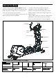
“PRODUCT PARTS DRAWING” 39
“PART LIST” NO. Item Name Q'ty NO. Item Name Q'ty CE-8.0i-1 Main Frame 1 CE-8.0i-36 End Cap (50x100mm) 4 CE-8.0i-2 Front Stabilizer 1 CE-8.0i-37 Pulley (95mm) 1 CE-8.0i-3 Rear Stabilizer 1 CE-8.0i-38 Pulley (190mm) 1 CE-8.0i-4 Upright Post 1 CE-8.0i-39 Magnet 1 CE-8.0i-5 Stationary Handlebar 1 CE-8.0i-40 Belt (1059mm J6) 1 CE-8.0i-6 Left Upper Handlebar 1 CE-8.0i-41 Belt (960mm J8) 1 CE-8.0i-7 Right Upper Handlebar 1 CE-8.0i-42 Square Plug 1 CE-8.
PART LIST” NO. Item Name Q'ty NO. Item Name Q'ty CE-8.0i-71 Washer (10×23×2.0t) 2 CE-8.0i-103 Nylon lock Nut (M10×p1.5×8t) 4 CE-8.0i-72 Washer (21×30×1.0t) 5 CE-8.0i-104 Nylon lock Nut (M10×p1.5) 2 2 CE-8.0i-105 Nut Cap (M17) 2 CE-8.0i-74 Screw (M3×10mm) 1 CE-8.0i-106 Adaptor 1 CE-8.0i-75 Screw (M4×20mm) 4 CE-8.0i-107 Sensor Wire & Stand 1 CE-8.0i-76 Screw (M5×18mm) 17 CE-8.0i-108 Upper Connection Wire 1 CE-8.0i-109 Middle Connection Wire 1 CE-8.
LIMITED WARRANTY 991214(1) LIMITED HOME USE WARRANTY – SMOOTH FITNESS Bikes Warranty Warranty Coverage: EVO Fitness and Smooth Fitness, Inc. ("Smooth Fitness") w arrants to the original ow ner that each new product to be free from defects in w orkmanship and material, under normal use and conditions. Period of Coverage: The Warranty on this product runs from the date of original purchase using the follow ing schedule: Model Name CE8.0LCi U.S.A. Only CE8.
Smooth Fitness th 780 5 Ave King of Prussia, PA 19406 Toll Free Customer Service: 1.888.800.1167 Website: www.smoothfitness.