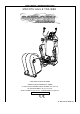
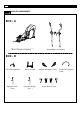
USER’S MANUAL - BEDIENUNGSANLEITUNG SMOOTH AGILE TRAINER USER WEIGHT LIMITATION: 350lbs MAXIMALES BENUTZERGEWICHT: 160 KG UK: TOLL FREE CUSTOMER SERVICE NUMBER: 0800-097 2100 DE: SERVICENUMBER: +49 (911) 810 59 24 SERIAL NUMBER (found on frame) – SERIENNUMMER (auf Rahmen) ST-MNL-WT100-SMEU-01
SMOOTH AGILE TRAINER INHALTSVERZEICHNIS – TABLE OF CONTENTS • English P. 03 • P.
www.smoothfitness.co.uk 3 PRECAUTIONS WARNING: To reduce the risk of burns, fire, electric shock, or injury to persons, read the following important precautions and information before operating the Elliptical Trainer. It is the responsibility of the owner to ensure that all users of this Elliptical Trainer are adequately informed of all warnings and precautions. • Use the Elliptical Trainer only as described in this manual. • Place on a level surface, with enough space behind it.
SMOOTH AGILE TRAINER POWER REQUIREMENTS IMPROPER CONNECTION OF THE EQUIPMENT GROUNDING CONNECTOR CAN RESULT IN A RISK OF AN ELECTRIC SHOCK. CHECK WITH A QUALIFIED ELECTRICIAN OR SERVICE MAN IF YOU ARE IN DOUBT AS TO WHETHER THE PRODUCT IS PROPERLY GROUNDED. DO NOT MODIFY THE PLUG PROVIDED WITH THE PRODUCT, IF IT WILL NOT FIT THE OUTLET; HAVE A PROPER OUTLET INSTALLED BY A QUALIFIED ELECTRICIAN. This Elliptical Trainer can be seriously damaged by sudden voltage changes in your home’s electrical power.
www.smoothfitness.co.uk 5 PREASSEMBLY Open the boxes: You are now ready to open the boxes of your new equipment. Make sure to inventory all of the parts that are included in the boxes. Check the Parts List for a full count of the number of parts included for this product to be assembled properly.
SMOOTH AGILE TRAINER SUPPLIED COMPONENTS This list identifies the major components you will use to assemble this product.
www.smoothfitness.co.uk SUPPLIED COMPONENTS This list identifies the major components you will use to assemble this product.
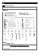
SMOOTH AGILE TRAINER SUPPLIED HARDWARE This list identifies the hardware you will use to assemble the product. To help distinguish between the various types of screws and bolts, use the scale below to measure them and compare them to the sizes listed.
www.smoothfitness.co.uk COMPLETE PARTS LIST Item No. Description Qty. Part No.
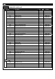
SMOOTH AGILE TRAINER COMPLETE PARTS LIST Item No. Description Qty. Part No. 214 Belt 1 AGILE-214 215 Aluminum Disk 1 AGILE-215 216 Crank 1 AGILE-216 217 Crank 25x186.
www.smoothfitness.co.uk COMPLETE PARTS LIST Item No. Description Qty. Part No.
SMOOTH AGILE TRAINER COMPLETE PARTS LIST Item No. Description Qty. Part No.
www.smoothfitness.co.uk COMPLETE PARTS LIST Item No. Description Qty. Part No. 435 Crank Axle Bushing 2 AGILE-435 436 M10 C Clip 6 AGILE-436 437 M12 C Clip 2 AGILE-437 438 M42 C Clip 2 AGILE-438 439 10 x 18 x T1.0 Fiber Washer 2 AGILE-439 440 15 x 8 x T2.0 Spring Washer 11 AGILE-440 441 10 x 16 x T2.0 Spring Washer 7 AGILE-441 442 20 x 6 x T2.0 Washer 3 AGILE-442 443 32 x 6 x T2.0 Washer 1 AGILE-443 444 35 x 14 x T2.0 Washer 2 AGILE-444 445 10 x 18 x T5.
SMOOTH AGILE TRAINER COMPLETE PARTS LIST Item No. Description Qty. Part No. 510 12 x 20 x 2 Spring Washer 2 AGILE-510 511 M10 Nylon Nut 1 AGILE-511 512 4 x 12mm Screw 10 AGILE-512 513 4 x 19mm Screw 6 AGILE-513 514 12 x 18 x 24.5mm Sleeve 2 AGILE-514 515 12 x 22 x 2 Washer 2 AGILE-515 516 M5 x 6mm Bolt 2 AGILE-516 517 M8 Nylon Nut 4 AGILE-517 518 8 x 20 x 1.
www.smoothfitness.co.uk COMPLETE PARTS LIST Item No. Description Qty. Part No.
SMOOTH AGILE TRAINER PARTS DIAGRAM MOST OF THE PARTS SHOWN HERE HAVE BEEN PRE-ASSEMBLED.
www.smoothfitness.co.uk PARTS DIAGRAM MOST OF THE PARTS SHOWN HERE HAVE BEEN PRE-ASSEMBLED.
SMOOTH AGILE TRAINER PARTS DIAGRAM MOST OF THE PARTS SHOWN HERE HAVE BEEN PRE-ASSEMBLED.
www.smoothfitness.co.uk 19 PARTS DIAGRAM MOST OF THE PARTS SHOWN HERE HAVE BEEN PRE-ASSEMBLED.
SMOOTH AGILE TRAINER PARTS DIAGRAM MOST OF THE PARTS SHOWN HERE HAVE BEEN PRE-ASSEMBLED.
www.smoothfitness.co.uk 21 PARTS DIAGRAM MOST OF THE PARTS SHOWN HERE HAVE BEEN PRE-ASSEMBLED.
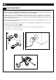
SMOOTH AGILE TRAINER ASSEMBLY STEP 1: Connect the Main Frame to Base Frame (A) Rotate Incline Frame (114) up to vertical position. (B) Place cardboard block under Main Frame tube to provide clearance to position Base Frame (104) for assembly. 507 X4 (C) Position Base Frame (104) under mounting bracket of the Main Frame (105) and align the 4 hole bolt pattern. (D) Remove cardboard block and lower Main Frame (105) onto Base Frame (104). Mounting Brackets should seat fully onto Base Frame (104).
www.smoothfitness.co.uk ASSEMBLY STEP 2: Connect the Incline Transmission Tube (A) Remove the Incline Transmission Tube Holder (322), and discard. (B) Rotate the Incline Frame (114) to align the bolt holes with the mating bolt holes in the Incline Transmission Tube-Front (115). 508 X1 (C) Assemble the Incline Transmission Tube-Front (115) to the Base Frame (104) with M10 x 62mm Allen Head Bolt (508) and M10 Nylon Nut (511) by 6mm Allen Key (D) and Wrench (F).
SMOOTH AGILE TRAINER ASSEMBLY STEP 3: Assemble the Undercarriage Covers NOTE:THE UNDERCARRIAGE COVER-LEFT(719) FITS OVER THE 8PIN POWER WIRE-LOWER (618). BE CAREFUL NOT TO DISCONNECT THE WIRE WHEN ASSEMBLING THE UNDERCARRIAGE COVER -LEFT (719). 512 X4 (A) Lift the Pedal Arm and assemble the Undercarriage Cover-Left (719) to the Base Frame (104), and secure using four 4 x 12 Screws (512). (B) Repeat the above procedure to assemble the right side.
www.smoothfitness.co.uk ASSEMBLY STEP 4: Assemble the Upright (A) Assemble the Upright-Left (110) and Upright-Right (111) to the Handlebar assembly and secure using two M8 x 56mm Allen Head Bolts (506). Do not completely tighten M8 x 56mm Allen Head Bolts until step C. (B) Place the Upright Assembly to the Base Frame (104) and secure with four M8 x 105 x 20mm Carriage Bolts (519), four M8 x 20 x 1.5mm Cup Washers (518) and N8 Nylon Nuts (517).
SMOOTH AGILE TRAINER ASSEMBLY STEP 5: Attach the Pivot Arm Covers (A) Thread the free end of the Pedal Swing Arm (120) through the hole in the Pivot Arm Cover-RL (707) and maneuver the Pivot Arm Cover-RL (120) to it’s final upright position. See the illustrations in STEP1, STEP2, and STEP3. 512 X4 (B) Assemble the Pivot Arm Cover-RR (706) and the Pivot Arm Cover (707) using the press-fit pins and secure to the frame using two 4 x 12mm Screws (512).
www.smoothfitness.co.uk ASSEMBLY STEP 6: Assemble the Pivot Cap 503 X2 717 X2 718 X2 NOTE: ALIGN THE 3 SNAP FIT TABS ON THE PEDAL SIDE CAPS (718) WITH THE 3 SNAP FIT ON THE PEDAL CAPS (717). (A) Assemble the Pivot Cap (717) to the Pedal Swing Arm (120) and secure using the M5 x 8mm Screw (503). (B) Press the Pedal Side Cap (718) to the Pedal Cap (717).
SMOOTH AGILE TRAINER ASSEMBLY STEP 7: Assemble the Console Support Tube NOTE: INSERT BOTH ENDS OF THE CONSOLE SUPPORT TUBE AT THE SAME TIME. (A) Connect the 8Pin Power Wire-Upper (616) to the 8Pin Power Wire-Middle (617). 504 X2 (B) Assemble the Consol Support Tube (103) to the Upright and Secure using the M8 x 20mm Allen Head Bolt (504).
www.smoothfitness.co.uk ASSEMBLY STEP 8: Assemble the Fixed Handlebar (A) Assemble the Fixed Handlebar (101) to the Console Support Tube (103) and Crossbar (102). (B) Secure the Fixed Handlebar (101) to the Crossbar (102) with two M8 x 20mm Allen Head Bolts (504). 504 X2 505 X2 (C) Secure the Fixed Handlebar (101) to the Console Support Tube (103) with two M8 x 40mm Allen Head Bolts (505).
SMOOTH AGILE TRAINER ASSEMBLY STEP 9: Tighten all Bolts (A) Tighten the M8 x 65mm Allen Head Cap Bolt by 6mm Allen Key (D) as show in STEP1. (B) Tighten the M8 x 105 x 20mm Allen Head Bolt (504) by Wrench (F) as show in STEP2.
www.smoothfitness.co.uk ASSEMBLY STEP 10: Assemble Upright Side Covers (A) Press the Upright Side Cover-Left (701) and Upright Side Cover-Right into the Upright sides.
SMOOTH AGILE TRAINER ASSEMBLY STEP 11: Connect the Pedal Arm to the Pedal Swing Arm (A) Slide the 20 x 78-M14 X 35mm Bolt (502) through the Pedal Arm-Right (107) and Pedal Swing Arm (120) the secure by 8mm Allen Key (E). (B) Repeat the above procedure to assemble the left side.
www.smoothfitness.co.uk 33 ASSEMBLY STEP 12: Connect the Moving Linkage (A) Connect the Action Handlebar-Right (109) to the Moving Linkage-Right (113) and secure using the 12 x 62-M10 x 20mm Bolt (501), 12 x 2 x 2mm Spring Washer (510), 12 x 22 x 2mm Washer (515), and 12 x 18 x 24.5 Sleeve (514) by 6mm Allen Key (D), as show in FIG1. (B). Repeat the above procedure to assemble the left side.
SMOOTH AGILE TRAINER ASSEMBLY STEP 13: Assemble the Pedal Arm Front Pivot Covers (A) Press the Pedal Arm Front Pivot Cover (721) into the ends of the Action Handlebar-Right (109) and Pedal Arm-Right (107). (B) Repeat the above procedure on the left side.
www.smoothfitness.co.uk ASSEMBLY STEP 14: Tighten Set Screws (A) Secure the M5 x 6mm Screw (516) to the Pedal Swing Arm (120) using the 2.5mm Allen Key (B).
SMOOTH AGILE TRAINER ASSEMBLY STEP 15: Assemble the Front Side Panels NOTE: THERE ARE 2 HOLES IN THE FRAME COMPONENTS THROUGH WHICH THE INSIDE AND OUTSIDE PLASTIC PANELS CONNECT TO EACHOTHER. USE THESE HOLES AS REFERENCES TO CORRECTLY POSITION THE PLASTIC PANELS. (A) Assemble the Front Side Panel-LL (709) and Front Side Panel-LR (710) to the left Upright and secure using one 4 x 12 Screw (512) and three 4 x 19mm Screws (513). 512 X2 513 X6 (B) Repeat the above procedure to assemble the right side.
www.smoothfitness.co.uk ASSEMBLY STEP 16: Assemble the Console NOTE: BE SURE TO PUSH THE WIRES INTO THE CONSOLE BEFORE YOU SECURE TO THE FRAME. (A) Connect the 8Pin Power Wire-Top (615) to the 8Pin Power Wire-Upper (616) as show in FIG1. (B) Assemble the Computer (312) to the Console Support Tube (103) and secure using two M6 x 40mm Screws (509). (C) Connect the Hand Pulse Sensor Wire-Upper (622) to Computer (312) as show in FIG2.
SMOOTH AGILE TRAINER ASSEMBLY STEP 17: Assemble Console Back Cover (A) Assemble the four Taper Fixing Inserts (326) to the Console Back Cover (703). (B) Assemble the Console Back Cover (703) to the Computer (312).
www.smoothfitness.co.uk 39 LEVEL ADJUSTMENT LEVEL ADJUSTMENT: To adjust the levelers follow these instructions: You will need someone to help you with this procedure, as you will need to tip, the AGILE Dynamic Motion Trainer while adjusting the levelers Tip the AGILE Dynamic Motion Trainer to the left/right. You will then see the LEVEL ADJUSTERS. These will need to be screwed either in or out to level the trainer. Repeat for the other side.
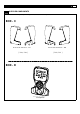
SMOOTH AGILE TRAINER LITE-TOUCH CONTROL OPERATION LITE-TOUCH CONTROL: The Intensity Level and Motion Level can be controlled using the Lite-Touch controls on the hand grips of the action handlebars. As the illustration indicates, the right Lite-Touch Controller controls the Motion Level and the left Lite-Touch Controller controls the Intensity Level. You can see the corresponding readouts on the console follow this same orientation.
www.smoothfitness.co.uk TRANSPORT INSTRUCTION TRANSPORT INSTRUCTIONS: To transport your AGILE Dynamic Motion Trainer simply lift the back end and roll it away to the desired location, as shown.
SMOOTH AGILE TRAINER MUSCLE CHART Targeted muscle groups: The exercise routine that is performed on this product will develop primarily lower body muscle groups. These muscle groups are shown in gray color on the chart below.
www.smoothfitness.co.uk 43 STRETCHING ROUTINE Warm up and cool down: A successful exercise program consists of a warm-up, aerobic exercise, and a cool-down. Do the entire program at least two and preferably three times a week, resting for a day between workouts. After several months, you can increase your workouts to four or five times per week. Warming up is an important part of your workout, and should begin every session.
SMOOTH AGILE TRAINER COMPUTER OPERATION I A B J C K D E F G L M H N DTAT DISPLAY-1 A I DTAT DISPLAY-2 INTENSITY LEVEL B J MOTION LEVEL INTENSITY PROFILE C K MOTION PROFILE PROGRAMS D L INTENSITY-UP EXPRESS MOTION E M START INTENSITY-DOWN F N MOTION-UP STOP / ENTER G MOTION-DOWN H
www.smoothfitness.co.uk 45 COMPUTER OPERATION DISPLAY FUNCTIONS: There are 6 display areas to show all the necessary information prior to and during the workout. INTENSITY LEVEL DISPLAY: Displays intensity level from 1 to 20. 8 x 16 DOT MATRIX INTENSITY LEVEL PROFILE DISPLAY: Displays all operating instructions prior to the workout and displays intensity level profiles during the workout. 8 x 8 DOT MATRIX MOTION LEVEL PROFILE DISPLAY: Displays motion level profiles during the workout.
SMOOTH AGILE TRAINER COMPUTER OPERATION continue the performance until the program finishes. If you leave the pedal stopped for over 3 minutes or press the STOP button twice, all the data will return to 0 and the computer will return to POWER ON status. ENGLISH/METRIC CONVERSION: The console display can show ENGLISH and METRIC information. The factory should have the proper setting on this for the different markets.
www.smoothfitness.co.uk 47 COMPUTER OPERATION WEIGHT display shows factory default setting “68(kgs)/150(Lb). Press INTENSITY UP/DOWN button to adjust the user weight and press STOP/ENTER to confirm. Press START button to start the target distance program. Distance counts down to 0, Time and Calories count up. Press INTENSITY UP/DOWN to adjust the resistance and press MOTION UP/DOWN to adjust the motion.
SMOOTH AGILE TRAINER COMPUTER OPERATION Press START button to start the INTENSITY INTERVAL program. Time counts down to 0, Distance and Calories count up. Dot Matrix display shows the pre-set INTENSITY and MOTION profile. Press INTENSITY UP/DOWN to adjust the resistance and press MOTION UP/DOWN to adjust the motion. Motion Interval Program When the console is in MOTION INTERVAL program set up, MOTION LEVEAL DISPLAY shows “L1”. This indicates the intensity level for the intervals.
www.smoothfitness.co.uk 49 COMPUTER OPERATION WEIGHT display shows factory default setting “68(kgs)/150(Lb). Press INTENSITY UP/DOWN button to adjust the user weight and press STOP/ENTER to confirm. Press START button to start the WATTS program. Time counts down to 0, Distance and Calories count up. Dot Matrix display shows the pre-set INTENSITY and MOTION profile.
SMOOTH AGILE TRAINER WARRANTY Read and follow the Assembly-instructions and the User’s-Manual before using this product. Warranty Coverage: Smooth Fitness GmbH ("Smooth Fitness") warrants to the original owner that each new product to be free from defects in workmanship and material. This warranty is limited on home use only.
www.smoothfitness.de 51 SICHERHEITSHINWEISE ACHTUNG: Um die Gefahr von Verbrennungen, Feuer, elektrischen Schlägen und sonstigen Verletzungen zu reduzieren, lesen Sie bitte die folgenden wichtigen Sicherheitshinweise und Informationen, bevor Sie den Elliptical Trainer benutzen. Es liegt in der Verantwortung des Eigentümers sicher zu stellen, dass alle Benutzer dieses Elliptical Trainers hinreichend über alle Sicherheitshinweise und Gefahren informiert wurden.
SMOOTH AGILE TRAINER STROMVERSORGUNG FEHLENDE ODER FEHLERHAFTE ERDUNG IHRES GERÄTS ERHÖHT DAS RISIKO EINES ELEKTROSCHOCKS. FALLS SIE ZWEIFEL HABEN, ZIEHEN SIE BITTE EINEN QUALIFIZIERTEN ELEKTRIKER HINZU UND LASSEN ÜBERPRÜFEN OB DAS GERÄT SACHGEMÄSS GEERDET IST. NEHMEN SIE KEINE EINGRIFFE AN DEN MITGELIEFERTEN NETZKABELN VOR. SOLLTEN DIE MITGELIEFERTEN NETZKABEL NICHT PASSEN KONTAKTIEREN SIE BITTE EINEN QUALIFIZIERTEN ELEKTRIKER ODER EIN ELEKTROFACHGESCHÄFT.
www.smoothfitness.de 53 VORBEREITUNG Öffnen Sie die Kartonagen: Nun können Sie die Kartonagen mit dem neuen Equipment öffnen. Verschaffen Sie sich einen Überblick über alle Teile die Sie in den Kartonagen finden. Vergleichen Sie diese mit der Einzelteil-Übersichtsliste um sicherzustellen, dass alle Teile in richtiger Anzahl vorhanden sind. Falls Sie ein Teil vermissen sollten, oder Fragen zum Aufbau haben, setzen Sie sich bitte mit dem Hersteller in Verbindung.
SMOOTH AGILE TRAINER LIEFERUMFANG Zu Ihrer Unterstützung haben wir hier alle Bauteile aufgeführt, die zum Aufbau dieses Produkts benötigt werden.
www.smoothfitness.de LIEFERUMFANG Zu Ihrer Unterstützung haben wir hier alle Bauteile aufgeführt, die zum Aufbau dieses Produkts benötigt werden.
SMOOTH AGILE TRAINER LIEFERUMFANG, EINZELTEILE UND WERKZEUGE Zu Ihrer Unterstützung haben wir hier alle Einzelteile und Werkzeuge aufgeführt, die zum Aufbau dieses Produkts benötigt werden. Diese Übersicht soll Ihnen dabei helfen, Einzelteile zu identifizieren, die Sie nicht zuordnen können. Der Maßstab unten soll beim messen und vergleichen von Teilen behilflich sein.
www.smoothfitness.de ERSATZTEILLISTE Item No. Description Qty. Part No. 100 101 Haltegriff 1 AGILE-101 102 Querträger 1 AGILE-102 103 Haltebügel 1 AGILE-103 104 Grundrahmen 1 AGILE-104 105 Hauptrahmen 1 AGILE-105 106 Fußstütze links 1 AGILE-106 107 Fußstütze rechts 1 AGILE-107 108 Bewegl. Handgriffstange - links 1 AGILE-108 109 Bewegl.
SMOOTH AGILE TRAINER ERSATZTEILLISTE Nr. Beschreibung Anz. Best. NR 214 Riemen 1 AGILE-214 215 Aluminium-Scheibe 1 AGILE-215 216 Kurbel 25x186.7 1 AGILE-216 217 Kurbel 25x186.
www.smoothfitness.de ERSATZTEILLISTE Nr. Beschreibung Anz. Best.
SMOOTH AGILE TRAINER ERSATZTEILLISTE Nr. Beschreibung Anz. Best.
www.smoothfitness.de ERSATZTEILLISTE Nr. 435 436 437 438 439 440 441 442 443 444 445 446 447 448 449 450 451 452 453 454 456 457 458 459 460 461 462 463 464 465 500 501 502 503 504 505 506 507 508 509 Beschreibung Anz. Best. NR. Distanzhülse M10 Sprengring M12 Sprengring M42 Sprengring 10 x 18 x T1.0 Unterlegscheibe 15 x 8 x T2.0 Unterlegscheibe 10 x 16 x T2.0 Unterlegscheibe 20 x 6 x T2.0 Unterlegscheibe 32 x 6 x T2.0 Unterlegscheibe 35 x 14 x T2.0 Unterlegscheibe 10 x 18 x T5.
SMOOTH AGILE TRAINER ERSATZTEILLISTE Nr. Beschreibung Anz. Best. NR. 510 12 x 20 x 2 Unterlegscheibe 2 AGILE-510 511 M10 selbsts. Mutter 1 AGILE-511 512 4 x 12mm Schraube 10 AGILE-512 513 4 x 19mm Schraube 6 AGILE-513 514 12 x 18 x 24.5mm Einsatz 2 AGILE-514 515 12 x 22 x 2 Unterlegscheibe 2 AGILE-515 516 M5 x 6mm Schraube 2 AGILE-516 517 M8 selbsts. Mutter 4 AGILE-517 518 8 x 20 x 1.
www.smoothfitness.de ERSATZTEILLISTE Nr. Beschreibung Anz. Best. NR.
SMOOTH AGILE TRAINER EXPLOSIONSZEICHNUNG Ein Großteil der hier abgebildeten Teile ist vom Werk aus vormontiert..
www.smoothfitness.de 65 EXPLOSIONSZEICHNUNG Ein Großteil der hier abgebildeten Teile ist vom Werk aus vormontiert..
SMOOTH AGILE TRAINER EXPLOSIONSZEICHNUNG Ein Großteil der hier abgebildeten Teile ist vom Werk aus vormontiert..
www.smoothfitness.de 67 EXPLOSIONSZEICHNUNG Ein Großteil der hier abgebildeten Teile ist vom Werk aus vormontiert..
SMOOTH AGILE TRAINER EXPLOSIONSZEICHNUNG Ein Großteil der hier abgebildeten Teile ist vom Werk aus vormontiert..
www.smoothfitness.de EXPLOSIONSZEICHNUNG Ein Großteil der hier abgebildeten Teile ist vom Werk aus vormontiert..
SMOOTH AGILE TRAINER AUFBAU ( SCHRITT 1: Verbinden von Hauptrahmen und Grundrahmen (A) Drehen Sie den Rahmen zur Höhenverstellung (114) senkrecht. (B) Schieben Sie einen Karton unter den Hauptrahmen um Freiraum für das montieren des Grundrahmens (104) zu schaffen. 507 X4 (C) Positionieren Sie den Grundrahmen (104) unter den Bügel des Hauptrahmens (105) und justieren Sie die 4 Schraublöcher. (D) Entfernen Sie den Karton und senken Sie den Hauptrahmen (105) auf den Grundrahmen (104).
www.smoothfitness.de AUFBAU SCHRITT 2 Montieren des Rohrs der Höhenverstellung (A) Entfernen Sie die Rohrfixierung (322) und entsorgen Sie diese. 508 X1 (B) Drehen Sie den Rahmen der Höhenverstellung (114) um die Schraublöcher mit denen am Rohr zur Höhenverstellung, vorderes (115) abzugleichen.
SMOOTH AGILE TRAINER AUFBAU SCHRITT 3 : Montieren der unteren Abdeckung BEACHTEN:DIE UNTERE ABDECKUNG-LINKS (719) PASST ÜBER DAS 8PIN COMPUTERKABEL;UNTERES (618). VORSICHT BITTE DIE KABEL BEIM MONTIEREN DER UNTEREN ABDECKUNG LINKS (719) NICHT TRENNEN 512 X4 (A) Heben Sie die Fußstütze und montieren Sie die untere Abdeckung, links (719) am Grundrahmen (104), befestigen Sie diese mit vier 4 x 12 Schrauben (512). (B) Wiederholen Sie den Vorgang auf der rechten Seite.
www.smoothfitness.de AUFBAU STEP 4: Assemble the Upright A) Montieren Sie den Ständer links (110) und Ständer, rechts (111) am Querträger und befestigen Sie diese mit zwei M8 x 56mm Schrauben (506). Ziehen Sie die M8 x 56mm Schrauben bis zum Schritt C nicht komplett fest. (B) Stecken Sie den Ständer auf den Grundrahmen (104) und befestigen Sie diesen mit vier M8 x 105 x 20mm Schrauben (519), vier M8 x 20 x 1.5mm Unterlegscheiben (518) und vier M 8 selbsts. Muttern (517).
SMOOTH AGILE TRAINER AUFBAU SCHRITT 5: Montieren der Verkleidung der beweglichen Handgriffe (A) Schieben Sie das freie Ende des Schwing-Arms der Fußstütze (120) durch das Loch in der Verkleidung, innen RL (707) und bringen diesen in die endgültige Position. Siehe Abb. in SCHRITT1, SCHRITT 2 und SCHRITT 3. (B) Montieren Sie die Verkleidung innen-RR (706) und die Verkleidung innen RL (707) durch die Presspassung und befestigen Sie diese am Rahmen mit zwei 4 x 12mm Schrauben (512).
www.smoothfitness.de AUFBAU SCHRITT 6:Montieren der Abdeckkappe 503 X2 717 X2 718 X2 BEACHTEN: GLEICHEN SIE DIE 3 SCHNAPPVERSCHLÜSSE DER ABDECKKAPPE (718) MIT DENEN DER ABDECKKAPPE (717). (A) Montieren Sie die Abdeckkappe (717) am Swing Arm für die Fußstütze (120) und befestigen Sie diese mit der M5 x 8mm Schraube (503). (B) Drücken Sie die Abdeckkappe (718) auf die Abdeckkappe (717).
SMOOTH AGILE TRAINER AUFBAU SCHRITT 7: Montieren des Haltebügels BEACHTEN: SETZEN SIE BEIDE ENDEN DES HALTEBÜGELS GLEICHZEITIG EIN. 504 (A) Verbinden Sie das 8 PIN Computerkabel oberes (616) mit dem 8 PIN Computerkabel mittleres (617). X2 (B) Befestigen Sie den Haltebügel (103) am Ständer mit der M8 x 20mm Schraube (504).
www.smoothfitness.de AUFBAU SCHRITT 8: Montieren des Haltegriffs (A) Montieren Sie den Haltegriff (101) am Haltebügel (103) und am Querträger (102). (B) Befestigen Sie den Haltegriff (101) am Querträger (102) mit zwei M8 x 20mm Schrauben (504). 504 X2 505 X2 (C) Befestigen Sie den Haltegriff (101) am Haltebügel (103) mit zwei M8 x 40mm Schrauben (505).
SMOOTH AGILE TRAINER AUFBAU (A) Ziehen Sie die M8 x 65mm Schraube mit dem 6 mm Imbus (D) fest, siehe Schritt 1. (B) Ziehen Sie die M8 x 20mm Schrauben (504) mit dem 5 mm Imbus (C) fest, siehe Schritt 2.
www.smoothfitness.de AUFBAU SCHRITT 10: Montieren der seitlichen Abdeckungen (A) Drücken Sie die Abdeckung seitlich, links (701) und die Abdeckung seitlich, rechts (702) an die Seiten der Ständer..
SMOOTH AGILE TRAINER AUFBAU SCHRITT 11: Montieren der Fußstütze am Swingarm der Fußstütze (A) Schieben Sie die 20 x 78-M14 X 35mm Schraube (502) durch die Fußstütze rechts (107) und den Schwungarm der Fußstütze (120); befestigen Sie diese mit dem 8mm Imbus (E). (B) Wiederholen Sie den Vorgang auf der linken Seite.
www.smoothfitness.de 81 AUFBAU SCHRITT 12: Montieren der Bügel zur Fußstütze (A) Verbinden Sie die bewegliche Handgriffstange rechts (109) mit dem Bügel zur Fußstütze (113) und befestigen Sie diese mit der 12 x 62-M10 x 20mm Schraube (501), der 12 x 2 x 2mm Unterlegscheibe (510), der 12 x 22 x 2mm Unterlegscheibe (515), and 12 x 18 x 24.5 Einsatz (514) mit dem 6mm Imbus (D) wie in Abbildung 1 dargestellt. 501 X2 510 X2 514 X2 (B) Wiederholen Sie den Vorgang auf der linken Seite. 515 X2 Abb.
SMOOTH AGILE TRAINER AUFBAU SCHRITT 13: Montieren der vorderen Abdeckung der Fußstützen (A) Drücken Sie die Abdeckung (721) in die Öffnungen der beweglichen Handriffstange rechts (109) und der Fußstütze rechts (107). (B) Wiederholen Sie den Vorgang auf der linken Seite.
www.smoothfitness.de AUFBAU SCHRITT 14: Festziehen aller Schrauben (A) Befestigen Sie die M5 x 6mm Schrauben (516) am Schwingarm der Fußstütze (120) mit dem 2.5mm Imbus (B).
SMOOTH AGILE TRAINER AUFBAU SCHRITT 15: Montieren der vorderen Außenverkleidung BEACHTEN: ES BEFINDEN SICH 2 LÖCHER IM RAHMEN DURCH DIE DIE INNERE UND ÄUSSERE PLASTIKVERKLEIDUNG MITEINANDER VERBUNDEN WIRD. BEZIEHEN SIE SICH AUF DIESE LÖCHER UM DIE VERKLEIDUNG RICHTIG ZU POSITIONIEREN. (A) Montieren Sie die Verkleidung, außen-LL (709) und die Verkleidung außenLR (710) am linken Ständer und befestigen Sie diese mit einer 4 x 12 Schraube (512) und drei 4 x 19mm Schrauben (513).
www.smoothfitness.de AUFBAU SCHRITT 16: Montieren des Computers BEACHTEN: STELLEN SIE SICHER, DASS ALLE KABEL IN DEN COMPUTER GESCHOBEN SIND BEVOR SIE IHN AM RAHMEN BEFESTIGEN. (A) Verbinden Sie das 8 Pin Computerkabel, oberes 1 (615) mit dem 8 Computerkabel, oberes 2 (616), siehe Abb. 1. (B) Montieren Sie das Computergehäuse, oberes (312) am Haltebügel (103) und befestigen Sie diese mit zwei M6 x 40mm Schrauben (509).
SMOOTH AGILE TRAINER AUFBAU SCHRITT 17: Montieren der hinteren Computerabdeckung (A) Montieren Sie die Gehäusezapfen (326) an der hinteren Computerabdeckung (703). (B) Montieren Sie die hintere Computerabdeckung (703) am Computergehäuse (312).
www.smoothfitness.de 87 STABILIESIERUNG STABILISIERUNG: Beachten Sie bei der Stabilisierung folgende Hinweise: Sie könnten bei diesem Schritt Hilfe benötigen, da Ihr AGILE Dynamic Motion Trainer gekippt werden muss um an die Stabilisatoren heran zu kommen. Kippen Sie das Gerät nach links oder rechts. Sie sehen jetzt die Verstellschrauben an der Unterseite. Drehen Sie die Verstellschrauben herein oder heraus, um das Niveau korrekt einzustellen. Es könnte hilfreich sein eine Wasserwaage zu verwenden.
SMOOTH AGILE TRAINER LITE-TOUCH CONTROL FUNKTION “LITE-TOUCH CONTROL”: Der Widerstand und die Ellipsenlänge können mit der Lite-Touch control auf den beweglichen Handgriffen reguliert werden. Wie auf der Abbildung zu sehen, ist der rechte Lite-Touch Control für die Ellipse und der linke Lite-Touch Control für den Widerstandsgrad zu verwenden. Wie ersichtlich folgen die entsprechenden Anzeigen des Computers der gleichen Seitenausrichtung.
www.smoothfitness.de TRANSPORTHINWEISE TRANSPORTHINWEISE Um Ihren AGILE Dynamic Motion Trainer zu transportieren heben Sie einfach das hintere Ende und schieben Sie das Gerät dann in die gewünschte Position.
SMOOTH AGILE TRAINER MUSKELÜBERSICHT Beanspruchte Muskelgruppen: Das Trainingsprogramm dieses Produkts beansprucht hauptsächlich die unteren Muskelgruppen des Körpers. Diese Muskelgruppen sind in der folgenden Übersicht grau hinterlegt.
www.smoothfitness.de 91 DEHNÜBUNGEN Aufwärmen und Abkühlen: Eine erfolgreiche Trainingseinheit besteht aus dem Aufwärmen, aeroben Übungen, und dem Abkühlen. Machen Sie das komplette Programm mindestens 2–3 Mal die Woche, mit jeweils einem Tag Pause zwischen den Trainingstagen. Nach einigen Monaten können Sie Ihr Training auf 4–5 Mal die Woche erhöhen. Das Aufwärmen ist ein sehr wichtiger Teil des Trainings und sollte jeder Einheit vorausgehen.
SMOOTH AGILE TRAINER COMPUTERBEDIENUNG I A B J C K D E F G L M H N DATEN ANZEIGE-1 A I DATEN ANEZIGE-2 WIDERSTAND B J ELLIPSENLÄNGE WIDERSTANDS PROFILE C K ELLIPSEN PROFILE PROGRAMME D L WIDERSTAND-AUF EXPRESS MOTION- E M START WIDERSTAND-AB F N ELLIPSE-AUF STOP / ENTER G ELLIPSE -AB H
www.smoothfitness.de 93 COMPUTERBEDIENUNG ANZEIGEFUNKTIONEN: Es befinden sich 6 Fenster auf dem Monitor, die Ihnen alle wichtigen Informationen vor und während des Trainings liefern WIDERSTAND - ANZEIGE: Zeigt die Widerstands-Stufen 1 bis 20. 8 x 16 DOT MATRIX WIDERSTANDS PROFIL ANZEIGE: Zeigt vor dem Training die Benutzerbefehle und während des Trainings die Widerstands-Profile. 8 x 8 DOT MATRIX ELLIPSENLÄNGEN ANZEIGE: Zeigt die Ellipsen Profile während des Trainings.
SMOOTH AGILE TRAINER COMPUTERBEDIENUNG ENGLISCHES / METRISCHES SYSTEM Der Computer des Elliptical Trainers kann sowohl metrische als auch englische Maße bzw. Einheiten anzeigen. Das sollte bereits für Ihr Land von Fabrik aus voreingestellt sein. Falls Sie dennoch zwischen den Systemen wechseln müssen, beachten Sie bitte die folgenden Anweisungen: 1. Schalten Sie den Computer ein. Drücken Sie gleichzeitig die STOP und ELLIPSE AUF Taste für 3 Sekunden.
www.smoothfitness.de 95 COMPUTERBEDIENUNG WEIGHT (Gewichtanzeige) zeigt die Werkseinstellung “68(kg)/150(lb). Drücken Sie die WIDERSTAND AUF/AB Taste um das Benutzergewicht zu ändern, bestätigen Sie dieses mit STOP/ENTER. Drücken Sie START um das Streckenvorgabeprogramm zu starten. Die Stecke zählt abwärts bis 0, Zeit und Kalorien zählen aufwärts. Drücken Sie die WIDERSTAND AUF/AB Taste um den Widerstand zu ändern und drücken Sie die ELLIPSE AUF/AB Taste um die Ellipsenlänge zu ändern.
SMOOTH AGILE TRAINER COMPUTERBEDIENUNG Drücken Sie die START Taste um das Widerstand Intervall Programm zu starten. Die Zeit zählt abwärts bis 0, Strecke und Kalorien zählen aufwärts. Die Dot Matrix Anzeige zeigt die Widerstands und Ellipsenprofile. Drücken Sie die WIDERSTAND AUF/AB Taste um den Widerstand zu ändern und drücken Sie die ELLISPEN AUF/AB Taste um die Bewegung zu ändern.
www.smoothfitness.de 97 COMPUTERBEDIENUNG WEIGHT (Gewichtsanzeige) zeigt die Werkseinstellung “68(kg)/150(Lob). Drücken Sie die WIDERSTAND AUF/AB Taste um das Benutzergewicht zu ändern und bestätigen Sie dieses mit STOP/ENTER. Drücken Sie die START Taste um das Leistungskontrolle Programm zu starten. Die Zeit zählt abwärts bis 0, Strecke und Kalorien zählen aufwärts. Die Dot Matrix Anzeige zeigt die Widerstands und Bewegunsprofile.
SMOOTH AGILE TRAINER Garantie Lesen und befolgen Sie unbedingt die Aufbau- und Betriebsanleitung bevor Sie das Gerät in Gebrauch nehmen. Garantieumfang: Smooth Fitness garantiert dem ursprünglichen Käufer, dass jedes neue Produkt frei von Verarbeitungs- und Materialfehlern ist.
Smooth Fitness LLC PO BOX 436 Farnborough GU14 4BS United Kingdom Phone: 0800-09 72 100 mail: info@smoothfitness.co.uk Website: www.smoothfitness.co.uk Smooth Fitness LLC Sandrartstrasse 28 90419 Nürnberg Germany Tel. + 49 (911) 810 59 24 Fax. + 49 (911) 36 68 05 93 mail: info@smoothfitness.de Website: www.smoothfitness.