
User's Manual


CONFIDENTIAL AND PROPRIETARY
The Information contained in this document shall remain the sole exclusive property of s.m.s smart microwave sensors GmbH and shall not
be disclosed by the recipient to third parties without prior consent of s.m.s smart microwave sensors GmbH in writing.
UMRR-0Axxxx Type31 Operational Description.docx Version 1 I Page 11 of 19 I August 22, 2013
6 Cables and connectors
6.1 Sensor connector
The used sensor connector is an 8-pin male circular connector (water proof IP67, series 712,
manufacturer Binder GmbH, Germany). A female counterpart has to be used to connect to
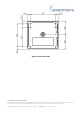
the sensor. The pin numbering of the female connector is shown in Figure 6 the pin out of
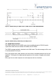
the connector is shown in Table 1.
Figure 6: Female counterpart of sensor connector (rear view)
Pin
Function
Wire color
1
RS485 L
Pink = RS_485_L
2
Ground
Blue = GND
3
RS485 H
Grey = RS_485_H
4
CAN_L
Yellow = CAN_L
5
CAN_H
Green = CAN_H
6
not connected
Brown = n.c.
7
+7V…+32V
Red = Vcc (+7V…+32V)
8
not connected
White = n.c.
Table 1: Sensor connector pin out Model UMRR-0Axxxx
Please note that in the standard configuration the sensor has no 120Ohms resistor on board
(CAN bus termination between CAN_L and CAN_H). The resistor is nevertheless required at
either end of a CAN bus and is in most cases integrated in the cable delivered along with the
sensor (if cable is manufactured by Smartmicro).