
User's Manual


CONFIDENTIAL AND PROPRIETARY
The Information contained in this document shall remain the sole exclusive property of s.m.s smart microwave sensors GmbH and shall not
be disclosed by the recipient to third parties without prior consent of s.m.s smart microwave sensors GmbH in writing.
UMRR-0F0002-1F0902-030B00 General Purpose USA Version 1 I Page 5 of 23 I November 13, 2014
4 General description
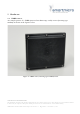
4.1 Sensor description
The main task of the UMRR is the detection of any reflectors in the field of view, to measure
the distance, the relative speed and the angle to the shortest reflector (and to other
reflectors), to detect motion and to track (filter) the results over time.
For this general purpose measurement application, range and relative radial speed and
the angle value of each reflector inside the antenna beam are measured and the results are
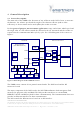
reported via the communication links cycle by cycle. For a block diagram of the sensor see
Figure 1.
Figure 1: Block diagram of the UMRR-0F sensor
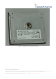
The UMRR sensor consists of two printed circuit boards: The DSP board and the RF
transceiver board.
The major component of the DSP board is the DSP TMS320F28335 which integrates flash
memory (for program code) and RAM. The DSP provides interfaces to external RAM,
EEPROM, CAN bus and RS485 (both for data communication). The Communication Processor
provides an Ethernet interface for data communication.
The DSP controls the RF transceiver board via an SPI interface.
RF transceiver board
MMIC
DSP board
Radar processor
(DSP TMS320F28335)
VCO
PLL
TX antenna
RX antennas
MxAmp
external
RAM
EEPROM
CAN
SPI (digital control)
analog
MxADC
McBSP
Program
Flash
internal
RAM
RS485
Mixer
SPI
DAC
Communic.
Processor
Ethernet
LAN
Clock
30 MHz
Clock
1 MHz
Clock
16MHz
25MHz