
User's Manual


CONFIDENTIAL AND PROPRIETARY
The Information contained in this document shall remain the sole exclusive property of s.m.s smart microwave sensors GmbH and shall not
be disclosed by the recipient to third parties without prior consent of s.m.s smart microwave sensors GmbH in writing.
UMRR-0F0002-1F0902-030B00 General Purpose USA Version 1 I Page 6 of 23 I November 13, 2014
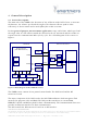
The RF transceiver board consists of transmit and receive antennae and the RF circuitry that
includes the radar MMIC SC3001.2. The radar MMIC generates the transmit signal and down
converts the receive signals into baseband. The analog baseband signals are then routed to
the DSP board and digitized by the DSP’s built-in ADC. The digital data are further processed
on the DSP.
The MMIC also features a PLL circuitry to calibrate and linearize the transmit frequency
ramps, a DAC for setting the VCO voltage (corresponding to the transmit frequency) and an
SPI interface for receiving the control signals from the DSP.
For the time of emission the device is one fixed point to point application.