Fan Speed Control with the EMC2102 Device Insert EVB graphic/photo here (this text can be removed on master page view) Copyright © 2007 SMSC or its subsidiaries. All rights reserved. Circuit diagrams and other information relating to SMSC products are included as a means of illustrating typical applications. Consequently, complete information sufficient for construction purposes is not necessarily given.
Fan Speed Control with the EMC2102 Device Table of Contents 1 Overview . . . . . . . . . . . . . . . . . . . . . . . . . . . . . . . . . . . . . . . . . . . . . . . . . . . . . . . . . . . . . . 6 2 Audience . . . . . . . . . . . . . . . . . . . . . . . . . . . . . . . . . . . . . . . . . . . . . . . . . . . . . . . . . . . . . . 6 3 References . . . . . . . . . . . . . . . . . . . . . . . . . . . . . . . . . . . . . . . . . . . . . . . . . . . . . . . . . . . . . 6 4 The Evaluation System . . . . .
Fan Speed Control with the EMC2102 Device 6.2.8 SMSC EMC2102 Using the Tested Parameters . . . . . . . . . . . . . . . . . . . . . . . . . . . . . . . . . . . . . . . . . . . . . 38 USER MANUAL 3 Revision 0.
Fan Speed Control with the EMC2102 Device List of Figures Figure 4.1 Figure 4.2 Figure 5.1 Figure 5.2 Figure 5.3 Figure 5.4 Figure 5.5 Figure 5.6 Figure 5.8 Figure 5.7 Figure 5.9 Figure 5.10 Figure 5.11 Figure 5.12 Figure 5.13 Figure 5.14 Figure 5.15 Figure 5.16 Figure 5.17 Figure 5.18 Figure 5.19 Figure 5.20 Figure 5.21 Figure 5.22 Figure 5.23 Figure 5.24 Figure 5.25 Figure 5.26 Figure 5.27 Figure 5.28 Figure 5.29 Figure 5.30 Figure 5.31 Figure 5.32 Figure 5.33 Figure 5.34 Figure 5.35 Figure 6.1 Figure 6.
Fan Speed Control with the EMC2102 Device List of Tables Table 5.1 Table 5.2 Table 5.3 Table 5.4 Register Change Summary for Experiment 2 Register Change Summary for Experiment 3 Register Change Summary for Experiment 4 Register Change Summary for Experiment 7 SMSC EMC2102 ..................................... ..................................... ..................................... ..................................... USER MANUAL 5 15 19 22 25 Revision 0.
Fan Speed Control with the EMC2102 Device 1 Overview SMSC has introduced a series of Environmental Monitoring and Control (EMC) devices with integrated fan control. This fan controller family devices feature the advanced closed-loop fan control technology developed by SMSC’s engineering team. This user manual provides detailed information about fan control features supported by one of those EMC devices -- EMC2102, with detailed hand-on experiments for configuring the devices in real applications.
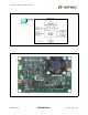
Fan Speed Control with the EMC2102 Device U SB C able P C w / C hipM an S oftw are E V B -E M C 2102 Figure 4.1 EMC2102 Fan Control Evaluation System Figure 4.2 EVB-EMC2102 Board SMSC EMC2102 USER MANUAL 7 Revision 0.
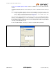
Fan Speed Control with the EMC2102 Device 5 Basic Operation Experiments In this chapter basic operation experiments will be provided to help users to get familiar with the system. 5.1 Experiment 1 - Manual Fan Control This experiment is designed to gain familiarity with both the EMC2102 device, and the application software, ChipMan. The ChipMan application can be used to configure the EMC2102 device and to monitor the status of the device. It includes tools to capture and plot data at rates up to 10Hz.
Fan Speed Control with the EMC2102 Device in Figure 5.4, "ChipMan Operation Window". Click on the HWM icon to show the different windows available. The EMC2102 WatchDog will have timed out at this point, and the on-board DC fan will be running at 100%. Note: Starting the ChipMan application without the USB cable/EVB connected to the PC, an error message "Supported company ID on device not found" will pop-up.
Fan Speed Control with the EMC2102 Device Figure 5.3 Selecting the Device and Master Controller Type Figure 5.4 ChipMan Operation Window Revision 0.
Fan Speed Control with the EMC2102 Device Notes: 1. The EVB-EMC2102 needs to be configured using the USB SMBus Bridge to work properly. If in the device selection window the Master Controller type is set to I/O Controller Hub then the "Supported company ID on device not found" message will pop-up again. 2. Disconnecting the USB cable and reconnecting it without restarting the ChipMan may cause register reading errors (all zeros).
Fan Speed Control with the EMC2102 Device Figure 5.5 Changing Fan Speed 5.1.3 Plotting From ChipMan The ChipMan software has the ability to plot register values in real-time, up to 10Hz continuous rate. To select a register to plot, highlight its name or value, and right-click. A menu with a single entry "Add register to Plot" will appear (Figure 5.6, "Plotting from the ChipMan"). Click the entry then a plot window should appear, with a legend on top.
Fan Speed Control with the EMC2102 Device Figure 5.7 Plot Windows The two plots shown in Figure 5.8, "Plot Examples" are in sync. If the scaled data is desired for analysis or archival, the data may be stored in a semi-colon separated text file from each of the plot windows. Simply select File Export, and enter a filename in the Save window. TACH Target (57h) Fan Driver Setting (51h) TACH Reading (58h) Figure 5.8 Plot Examples 5.
Fan Speed Control with the EMC2102 Device 5.2.2 Basic RPM Based Fan Control The EMC2102 defaults will enable closed-loop operation. Prior to other options, examine the various parameters on ChipMan window page 3: Fan Settings. The registers of most interest are the FAN Minimum Drive (55h), and Valid Tach Count (56h). The closed-loop controller will not drive below the minimum drive value, and will not respond to a TACH Target RPM speed less than the speed defined by the Valid Tach Count register.
Fan Speed Control with the EMC2102 Device Fan was covered The cover was removed Figure 5.10 Effects of Loading 5.2.4 Register Change Summary Table 5.1, "Register Change Summary for Experiment 2" lists all register value changes from the default cmf load to accomplish the tests. Table 5.
Fan Speed Control with the EMC2102 Device 5.3 Experiment 3 - Spin-up Configuration Options This experiment is designed to gain familiarity with the various spin-up options available in the EMC2102 devices. This experiment will discuss the effects of Spin-Up Time and Spin-Up Levels. These parameters are important to ensure a valid start, while minimizing the turn-on overshoot for initial low RPM settings. (More examples regarding these two parameters can be found in Section 5.7.
Fan Speed Control with the EMC2102 Device the 60% drive the register 51h value is 153d or 99h, and for 75% it is 191d or BFh. Those two drive settings will run a DC fan at two different speeds and we will call them rpm60 and rpm75. Depending on the fan, the speed for the same drive setting will vary. All data and plot examples in this document were taken using an EVB-EMC2102 board with the onboard DC fan. This fan has an rpm60 of 4500 rpm, and an rpm75 of 5650 rpm. 5.3.
Fan Speed Control with the EMC2102 Device Invalid TACH Count Figure 5.13 60% Spin Level Setting Note: When a fan starts, the first TACH count captured by the EMC2102 may not reflect the fan’s speed correctly, since the counting clock (32.768 kHz) could only partially fill the counting window, which will cause a higher speed reading.
Fan Speed Control with the EMC2102 Device 5.3.6 Register Change Summary Table 5.2, "Register Change Summary for Experiment 3" lists all register value changes from the default cmf load to accomplish the tests. Table 5.2 Register Change Summary for Experiment 3 REGISTER NAME FAN Spin Up Configuration SMSC EMC2102 ADDRESS 53h DEFAULT VALUE NEW VALUE 01h (00000001b) 03h SPINUP_TIME of 2.0 sec 05h Change the LEVEL from 60% to 75% COMMENT USER MANUAL 19 Revision 0.
Fan Speed Control with the EMC2102 Device 5.4 Experiment 4 - RPM Drive Mode Rate Controls This experiment is designed to gain familiarity with the rate control options available in the EMC2102 devices. This experiment will discuss the effects of Maximum Fan Step and Update rate that can be used to control the ramp rate of a fan. The two parameters ensure the fan reaches the desired drive in a reasonable time with no oscillations.
Fan Speed Control with the EMC2102 Device UPDATE = 100 ms UPDATE = 400 ms Figure 5.16 Default Step Size with Different UPDATE Settings In the next experiment (Figure 5.17, "Default UPDATE with Different Step Size Settings"), two different maximum step sizes, 16 and 63, were used. with the 63 STEP SIZE setting, the output takes less steps (updates) from 4000 rpm to 7500 rpm because it gives the fan more power to follow the desired rpm settings. STEp SIZE = 63 STEp SIZE = 16 Figure 5.
Fan Speed Control with the EMC2102 Device Figure 5.18 Exceptionally Slow Rate 5.4.3 Register Change Summary Table 5.3, "Register Change Summary for Experiment 4" lists all register value changes from the default cmf load to accomplish the tests. Table 5.3 Register Change Summary for Experiment 4 REGISTER NAME ADDRESS DEFAULT VALUE NEW VALUE FAN Step 54h 10h 01h Fan Configuration 52h CBh C8h, CFh Revision 0.
Fan Speed Control with the EMC2102 Device 5.5 Experiment 5 - Optimizing RPM Control Response This experiment is designed to gain familiarity with the parameters that affect the closed-loop controller implemented in the EMC2102. All these registers are located on the Fan Setting page in ChipMan. This experiment will go through each register, examining the effects of parametric changes on the closed-loop controller in RPM mode. 5.5.
Fan Speed Control with the EMC2102 Device 5.5.3 FAN Minimum Drive Register (55h) and Valid TACH Count (56h) These two registers assist the user in defining the operational environment for a given fan. The Minimum Drive register is an absolute minimum value the RPM controller may drive to in an attempt to achieve low RPM settings. The Valid Tach Count register is used to compare against the Tach Target register. No value less than the Valid Tach Count will be accepted by the controller.
Fan Speed Control with the EMC2102 Device 5.5.4 Register Change Summary Table 5.4, "Register Change Summary for Experiment 7" lists all register value changes from the default cmf load to accomplish the tests. Table 5.
Fan Speed Control with the EMC2102 Device 5.6 Experiment 6 - Limits and Alerts This experiment is designed to gain familiarity with the control registers for generating fan related alarms and alerts associated with the EMC2102. The CMF file for this experiment is EMC2102_default.cmf. 5.6.1 General Setup For all these tests, the Fan Drive Setting register (51h), the TACH Target register (57h) and the TACH Reading registers (58h) are selected to plot.
Fan Speed Control with the EMC2102 Device TACH Target (57h) Fan Drive Setting (51h) TACH Reading (58h) Stall Interrupt Status 2 (23h) Figure 5.22 Fan Spin and Stall 5.6.3 Register Change Summary All register values are default for the tests in this section. SMSC EMC2102 USER MANUAL 27 Revision 0.
Fan Speed Control with the EMC2102 Device 5.7 Experiment 7 - Troubleshooting 5.7.1 Repetitious Spin-up Routine Caused by Incorrect Settings At the end of spin-up routine (see Section 5.3.1, "Fan Control Parameters"), the EMC2102 checks the TACH Reading register (58h). If the value in this register is greater than the Valid TACH Count (56h), which means the fan is running at a speed slower than the minimum valid speed, the spin-up routine will be restarted (Figure 5.
Fan Speed Control with the EMC2102 Device Fan Speed (RPM) RPM for 100% Drive Target Speed Valid Speed rpm60 or rpm75 Fan Speed ¼ of Spin Up Time Spin Up Time Check TACH Figure 5.24 Theoretical Plot of Case 1 Spin Up Level Changed to 75% Figure 5.25 Spin-up Case 1 Fix 1 If the fan is already set to 75% level, we will need to lower the valid speed (function of 56h, Valid TACH) to a value below the rpm75, to fix the problem.
Fan Speed Control with the EMC2102 Device Valid Speed = 6000 rpm Fan Drive Setting (51h) Valid Speed = 5800 rpm Valid Speed = 5580 rpm Figure 5.26 Spin-up Case 1 Fix 2 5.7.1.2 Case 2 - Valid RPM << Target RPM < Spin-up Level RPM In this case, the target speed is smaller than the spin-up level speed (rpm60 or rpm75) and is much bigger than the valid speed. The theoretical plot of this situation is shown in Figure 5.27, "Theoretical Plot of Case 2".
Fan Speed Control with the EMC2102 Device Fan Drive Setting (51h) Figure 5.28 Spin-up Case 2 5.7.1.3 Case 3 - Valid RPM =< Target RPM << Spin-up Level RPM In this case, the target speed is only a little greater than the valid speed, and both of them are much smaller than the spin-up level speed (rpm60 or rpm75). The theoretical plot of this situation is shown in Figure 5.29, "Theoretical Plot of Case 3".
Fan Speed Control with the EMC2102 Device Using the EVB-EMC2102 to test this situation with rpm75 (~5650 rpm), simply set the Valid TACH register (56h) with 4500 rpm, set the UPDATE (52h[2:0]) = 100ms and start the fan with 4700 rpm, the spin-up routine starts over ‘and over (Figure 5.30, "Spin-up Case 3"). To fix this problem, change the UPDATE (52h[2:0]) back to 400 ms. It will give the fan more time to reach the speed of the previous step and reduce the overshoot/undershoot.
Fan Speed Control with the EMC2102 Device 5.7.1.4 Case 4 - 4.Valid RPM < Spin-up Level RPM (rpm60 or rpm75) < Target RPM In this case, the spin-up level speed (rpm60 or rpm75) is greater than the valid speed and smaller than the target speed, as shown in Figure 5.32, "Theoretical Plot of Case 4". At the end of spin-up routine, the closed-loop control will drive the fan up to reach the target, therefore the fan speed will never be lower than the valid speed.
Fan Speed Control with the EMC2102 Device 5.7.1.5 Case 5 - Correct RPM Relationships with a Slow Response DC Fan In this case, the spin-up routine is too short to make the fan reach a speed higher than the valid speed. Since the EMC2102 cannot detect a valid TACH at the end of spin-up routine, it will try to restart the fan. Depending on the fan, it is possible that after several spin-up cycles, the fan can reach the valid speed and operate normally.
Fan Speed Control with the EMC2102 Device 6 Appendix 6.1 DC Fan Basics - Poles, Tach Meter Pulses and Edges An n-pole fan has n pairs of North-South magnetic poles which are generated by electromagnet coils. At anytime, only one pair of coils are driven and which coil pair gets driven is determined by a component called Hall Sensor. The architecture of a typical 2-pole DC fan is shown in Figure 6.1, "A Typical 2-pole DC Fan".
Fan Speed Control with the EMC2102 Device Note: Although users can set the number of edges (in register 52h) to either 3, 5, 7 or 9, it is strongly recommended using the default value 5 while driving a 2-pole DC fan. This equal to one complete fan revolution for a 2-pole fan. 5 EDGES 3 EDGES Fan Tach Signal 7 EDGES 32.768kHz Clock n-EDGE WINDOW TWINDOW Figure 6.3 Fan TACH Measurement With EMC2102 ChipMan translates TACH counts to the RPM value and displays the fan speed.
Fan Speed Control with the EMC2102 Device 6.2.2 6.2.3 6.2.4 6.2.5 6.2.6 Verify the device is in Manual Mode (52h[7] = 0) Set the Correct LIMIT2K Value Register 52h (FAN Configuration) bit 6 (LIMIT2K) is a fan dependent parameter as discussed in Section 5.5.2, "Fan Configuration Register (52h)".
Fan Speed Control with the EMC2102 Device 6.2.7 6.2.