
- Standard Microsystems Ethernet Transceiver Specification Sheet

MII/RMII 10/100 Ethernet Transceiver with HP Auto-MDIX and flexPWR
®
Technology in a Small Footprint
Datasheet
SMSC LAN8710/LAN8710i 17 Revision 1.0 (04-15-09)
DATASHEET
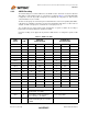
3.3 Management Signals
3.4 General Signals
3.5 10/100 Line Interface Signals
LED2/
nINTSEL
2IOPULED2 – Link Speed LED Indication.
See Section 5.3.7 for a description of LED modes.
nINTSEL: On power-up or external reset, the mode of the nINT/TXER/TXD4
pin is selected.
When LED2/nINTSEL is floated or pulled to VDDIO, nINT is selected for
operation on pin nINT/TXER/TXD4 (default).
When LED2/nINTSEL is pulled low to VSS through a resistor, TXER/TXD4
is selected for operation on pin nINT/TXER/TXD4.
See Section 4.10 for additional information.
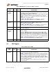
Table 3.4 Management Signals 32-QFN
SIGNAL
NAME
32-QFN
PIN # TYPE DESCRIPTION
MDIO 16 IOD8 Management Data Input/OUTPUT: Serial management data input/output.
MDC 17 I8 Management Clock: Serial management clock.
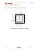
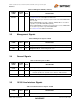
Table 3.5 General Signals 32-QFN
SIGNAL
NAME
32-QFN
PIN # TYPE DESCRIPTION
XTAL1/
CLKIN
5ICLKClock Input: Crystal connection or external clock input.
XTAL2 4 OCLK Clock Output: Crystal connection.
Float this pin when an external clock is driven to XTAL1/CLKIN.
nRST 19 IOPU External Reset: Input of the system reset. This signal is active LOW.
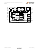
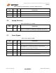
Table 3.6 10/100 Line Interface Signals 32-QFN
SIGNAL
NAME
32-QFN
PIN # TYPE DESCRIPTION
TXP 29 AIO Transmit/Receive Positive Channel 1.
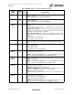
Table 3.3 LED Signals 32-QFN (continued)
SIGNAL
NAME
32-QFN
PIN # TYPE DESCRIPTION