
- Standard Microsystems Ethernet Transceiver Specification Sheet

MII/RMII 10/100 Ethernet Transceiver with HP Auto-MDIX and flexPWR
®
Technology in a Small Footprint
Datasheet
Revision 1.0 (04-15-09) 44 SMSC LAN8710/LAN8710i
DATASHEET
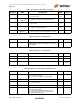
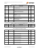
17.6 ALTINT Alternate Interrupt Mode.
0 = Primary interrupt system enabled (Default).
1 = Alternate interrupt system enabled.
See Section 5.2, "Interrupt Management," on page 47.
RW 0
17.5:4 Reserved Write as 0, ignore on read. RW 00
17.3 PHYADBP 1 = PHY disregards PHY address in SMI access
write.
RW 0
17.2 Force
Good Link Status
0 = normal operation;
1 = force 100TX- link active;
Note: This bit should be set only during lab testing
RW 0
17.1 ENERGYON ENERGYON – indicates whether energy is detected
on the line (see Section 5.3.5.2, "Energy Detect
Power-Down," on page 50); it goes to “0” if no valid
energy is detected within 256ms. Reset to “1” by
hardware reset, unaffected by SW reset.
RO X
17.0 Reserved Write as 0. Ignore on read. RW 0
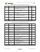
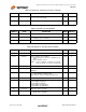
Table 5.30 Register 18 - Special Modes
ADDRESS NAME DESCRIPTION MODE DEFAULT
18.15 Reserved Write as 0, ignore on read. RW 0
18.14 MIIMODE MII Mode: set the mode of the digital interface, as
described in Section 5.3.9.3:
0 – MII interface.
1 – RMII interface
RW,
NASR
X
18.13:8 Reserved Write as 0, ignore on read. RW,
NASR
000000
18.7:5 MODE Transceiver Mode of operation. Refer to Section
5.3.9.2, "Mode Bus – MODE[2:0]," on page 53 for
more details.
RW,
NASR
XXX
18.4:0 PHYAD PHY Address.
The PHY Address is used for the SMI address and for
the initialization of the Cipher (Scrambler) key. Refer
to Section 5.3.9.1, "Physical Address Bus -
PHYAD[2:0]," on page 52 for more details.
RW,
NASR
PHYAD
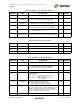
Table 5.31 Register 26 - Symbol Error Counter
ADDRESS NAME DESCRIPTION MODE DEFAULT
26.15:0 Sym_Err_Cnt 100Base-TX receiver-based error register that
increments when an invalid code symbol is received
including IDLE symbols. The counter is incremented
only once per packet, even when the received packet
contains more than one symbol error. The 16-bit
register counts up to 65,536 (2
16
) and rolls over to 0
if incremented beyond that value. This register is
cleared on reset, but is not cleared by reading the
register. It does not increment in 10Base-T mode.
RO 0
Table 5.29 Register 17 - Mode Control/Status (continued)
ADDRESS NAME DESCRIPTION MODE DEFAULT