LAN8710/LAN8710i MII/RMII 10/100 Ethernet Transceiver with HP Auto-MDIX and flexPWR® Technology in a Small Footprint PRODUCT FEATURES Datasheet Highlights Single-Chip Ethernet Physical Layer Transceiver (PHY) Comprehensive flexPWR® Technology — — — — Key Benefits — — — — — — — — Flexible Power Management Architecture Power savings of up to 40% compared to competition LVCMOS Variable I/O voltage range: +1.6V to +3.6V Integrated 1.
MII/RMII 10/100 Ethernet Transceiver with HP Auto-MDIX and flexPWR® Technology in a Small Footprint Datasheet ORDER NUMBER(S): LAN8710A-EZK FOR 32-PIN, QFN LEAD-FREE ROHS COMPLIANT PACKAGE (0 TO +85°C TEMP) LAN8710Ai-EZK FOR 32-PIN, QFN LEAD-FREE ROHS COMPLIANT PACKAGE (-40 TO +85°C TEMP) LAN8710A-EZK-TR FOR 32-PIN, QFN LEAD-FREE ROHS COMPLIANT PACKAGE (0 TO +85°C TEMP) LAN8710Ai-EZK-TR FOR 32-PIN, QFN LEAD-FREE ROHS COMPLIANT PACKAGE (-40 TO +85°C TEMP) Reel Size is 4000 80 ARKAY DRIVE, HAUPPAUGE, NY 1
MII/RMII 10/100 Ethernet Transceiver with HP Auto-MDIX and flexPWR® Technology in a Small Footprint Datasheet Table of Contents Chapter 1 Introduction . . . . . . . . . . . . . . . . . . . . . . . . . . . . . . . . . . . . . . . . . . . . . . . . . . . . . . . 9 1.1 1.2 1.3 General Terms and Conventions . . . . . . . . . . . . . . . . . . . . . . . . . . . . . . . . . . . . . . . . . . . . . . . . . . . 9 General Description . . . . . . . . . . . . . . . . . . . . . . . . . . . . . . . . . . . . . . . .
MII/RMII 10/100 Ethernet Transceiver with HP Auto-MDIX and flexPWR® Technology in a Small Footprint Datasheet 4.8 4.9 4.10 4.11 4.12 4.13 4.14 4.7.1 Parallel Detection . . . . . . . . . . . . . . . . . . . . . . . . . . . . . . . . . . . . . . . . . . . . . . . . . . . . . . 4.7.2 Re-starting Auto-negotiation . . . . . . . . . . . . . . . . . . . . . . . . . . . . . . . . . . . . . . . . . . . . . . 4.7.3 Disabling Auto-negotiation. . . . . . . . . . . . . . . . . . . . . . . . . . . . . . . . . . . . .
MII/RMII 10/100 Ethernet Transceiver with HP Auto-MDIX and flexPWR® Technology in a Small Footprint Datasheet 8.2 8.1.3 Twisted-Pair Interface Diagram . . . . . . . . . . . . . . . . . . . . . . . . . . . . . . . . . . . . . . . . . . . . 74 Magnetics Selection . . . . . . . . . . . . . . . . . . . . . . . . . . . . . . . . . . . . . . . . . . . . . . . . . . . . . . . . . . . . 75 Chapter 9 Package Outline . . . . . . . . . . . . . . . . . . . . . . . . . . . . . . . . . . . . . . . . . . . . . . . . .
MII/RMII 10/100 Ethernet Transceiver with HP Auto-MDIX and flexPWR® Technology in a Small Footprint Datasheet List of Figures Figure 1.1 Figure 1.2 Figure 2.1 Figure 4.1 Figure 4.2 Figure 4.3 Figure 4.4 Figure 4.5 Figure 4.6 Figure 4.7 Figure 4.8 Figure 5.1 Figure 5.2 Figure 5.3 Figure 6.1 Figure 6.2 Figure 6.3 Figure 6.4 Figure 6.5 Figure 6.6 Figure 6.7 Figure 6.8 Figure 6.9 Figure 6.10 Figure 8.1 Figure 8.2 Figure 8.3 Figure 8.4 Figure 8.5 Figure 9.1 Figure 9.1 Figure 9.2 Figure 9.
MII/RMII 10/100 Ethernet Transceiver with HP Auto-MDIX and flexPWR® Technology in a Small Footprint Datasheet List of Tables Table 2.1 LAN8710/LAN8710i 32-PIN QFN Pinout . . . . . . . . . . . . . . . . . . . . . . . . . . . . . . . . . . . . . . . . . Table 3.1 Buffer Types . . . . . . . . . . . . . . . . . . . . . . . . . . . . . . . . . . . . . . . . . . . . . . . . . . . . . . . . . . . . . . Table 3.2 MII/RMII Signals 32-QFN . . . . . . . . . . . . . . . . . . . . . . . . . . . . . . . . . . . . . . .
MII/RMII 10/100 Ethernet Transceiver with HP Auto-MDIX and flexPWR® Technology in a Small Footprint Datasheet Table 6.1 SMI Timing Values. . . . . . . . . . . . . . . . . . . . . . . . . . . . . . . . . . . . . . . . . . . . . . . . . . . . . . . . . . Table 6.2 100M MII Receive Timing Values . . . . . . . . . . . . . . . . . . . . . . . . . . . . . . . . . . . . . . . . . . . . . . Table 6.3 100M MII Transmit Timing Values . . . . . . . . . . . . . . . . . . . . . . . . . . . . . . . . . . . . . . . . .
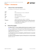
MII/RMII 10/100 Ethernet Transceiver with HP Auto-MDIX and flexPWR® Technology in a Small Footprint Datasheet Chapter 1 Introduction 1.1 General Terms and Conventions The following is list of the general terms used in this document: BYTE 8-bits FIFO First In First Out buffer; often used for elasticity buffer MAC Media Access Controller MII Media Independent Interface RMIITM Reduced Media Independent InterfaceTM N/A Not Applicable X Indicates that a logic state is “don’t care” or undefined.
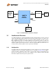
MII/RMII 10/100 Ethernet Transceiver with HP Auto-MDIX and flexPWR® Technology in a Small Footprint Datasheet 10/100 Ethernet MAC MDI Transformer RJ45 LAN8710 MII or RMII Ethernet Transceiver MODE LED Status Crystal or Clock Osc Figure 1.1 LAN8710/LAN8710i System Block Diagram 1.3 Architectural Overview The LAN8710/LAN8710i is compliant with IEEE 802.3-2005 standards (MII Pins tolerant to 3.6V) and supports both IEEE 802.3-2005 compliant and vendor-specific register functions.
MII/RMII 10/100 Ethernet Transceiver with HP Auto-MDIX and flexPWR® Technology in a Small Footprint Datasheet MODE0 MODE1 MODE2 nRST MODE Control AutoNegotiation 10M Tx Logic Reset Control SMI RMIISEL 10M Transmitter HP Auto-MDIX TXP / TXN Transmit Section 100M Tx Logic Management Control RXP / RXN 100M Transmitter MDIX Control TXD[0:3] TXEN TXER TXCLK CRS COL/CRS_DV RMII / MII Logic RXD[0:3] RXDV RXER RXCLK 100M Rx Logic MDC MDIO DSP System: Clock Data Recovery Equalizer Analog-toDigi
MII/RMII 10/100 Ethernet Transceiver with HP Auto-MDIX and flexPWR® Technology in a Small Footprint Datasheet Chapter 2 Pin Configuration RBIAS RXP RXN TXP TXN VDD1A RXDV TXD3 32 31 30 29 28 27 26 25 Package Pin-out Diagram and Signal Table VDD2A 1 24 TXD2 LED2/nINTSEL 2 23 TXD1 LED1/REGOFF 3 22 TXD0 21 TXEN 20 TXCLK 19 nRST 18 nINT/TXER/TXD4 17 MDC 14 15 16 CRS MDIO RXD2/RMIISEL COL/CRS_DV/MODE2 VSS 13 8 RXER/RXD4/PHYAD0 RXD3/PHYAD2 12 7 11 6 VDDIO
MII/RMII 10/100 Ethernet Transceiver with HP Auto-MDIX and flexPWR® Technology in a Small Footprint Datasheet Table 2.1 LAN8710/LAN8710i 32-PIN QFN Pinout PIN NO. PIN NAME PIN NO.
MII/RMII 10/100 Ethernet Transceiver with HP Auto-MDIX and flexPWR® Technology in a Small Footprint Datasheet Chapter 3 Pin Description This chapter describes the signals on each pin. When a lower case “n” is used at the beginning of the signal name, it indicates that the signal is active low. For example, nRST indicates that the reset signal is active low. The buffer type for each signal is indicated in the TYPE column, and a description of the buffer types is provided in Table 3.1. Table 3.
MII/RMII 10/100 Ethernet Transceiver with HP Auto-MDIX and flexPWR® Technology in a Small Footprint Datasheet Table 3.2 MII/RMII Signals (continued) 32-QFN (continued) SIGNAL NAME 32-QFN PIN # TYPE TXD2 24 I8 Transmit Data 2: The MAC transmits data to the transceiver using this signal in MII Mode. This signal should be grounded in RMII Mode. TXD3 25 I8 Transmit Data 3: The MAC transmits data to the transceiver using this signal in MII Mode. This signal should be grounded in RMII Mode.
MII/RMII 10/100 Ethernet Transceiver with HP Auto-MDIX and flexPWR® Technology in a Small Footprint Datasheet Table 3.2 MII/RMII Signals (continued) 32-QFN (continued) SIGNAL NAME 32-QFN PIN # TYPE DESCRIPTION RXER/ RXD4/ PHYAD0 13 IOPD RXER – Receive Error: Asserted to indicate that an error was detected somewhere in the frame presently being transferred from the transceiver. The RXER signal is optional in RMII Mode.
MII/RMII 10/100 Ethernet Transceiver with HP Auto-MDIX and flexPWR® Technology in a Small Footprint Datasheet Table 3.3 LED Signals 32-QFN (continued) SIGNAL NAME 32-QFN PIN # TYPE LED2/ nINTSEL 2 IOPU DESCRIPTION LED2 – Link Speed LED Indication. See Section 5.3.7 for a description of LED modes. nINTSEL: On power-up or external reset, the mode of the nINT/TXER/TXD4 pin is selected. When LED2/nINTSEL is floated or pulled to VDDIO, nINT is selected for operation on pin nINT/TXER/TXD4 (default).
MII/RMII 10/100 Ethernet Transceiver with HP Auto-MDIX and flexPWR® Technology in a Small Footprint Datasheet Table 3.6 10/100 Line Interface Signals (continued) 32-QFN (continued) SIGNAL NAME 32-QFN PIN # TYPE TXN 28 AIO Transmit/Receive Negative Channel 1. RXP 31 AIO Transmit/Receive Positive Channel 2. RXN 30 AIO Transmit/Receive Negative Channel 2. 3.6 DESCRIPTION Analog Reference Table 3.
MII/RMII 10/100 Ethernet Transceiver with HP Auto-MDIX and flexPWR® Technology in a Small Footprint Datasheet Chapter 4 Architecture Details 4.
MII/RMII 10/100 Ethernet Transceiver with HP Auto-MDIX and flexPWR® Technology in a Small Footprint Datasheet 4.2.2 4B/5B Encoding The transmit data passes from the MII block to the 4B/5B encoder. This block encodes the data from 4-bit nibbles to 5-bit symbols (known as “code-groups”) according to Table 4.1. Each 4-bit data-nibble is mapped to 16 of the 32 possible code-groups. The remaining 16 code-groups are either used for control information or are not valid.
MII/RMII 10/100 Ethernet Transceiver with HP Auto-MDIX and flexPWR® Technology in a Small Footprint Datasheet Table 4.
MII/RMII 10/100 Ethernet Transceiver with HP Auto-MDIX and flexPWR® Technology in a Small Footprint Datasheet 4.2.6 100M Phase Lock Loop (PLL) The 100M PLL locks onto reference clock and generates the 125MHz clock used to drive the 125 MHz logic and the 100Base-Tx Transmitter.
MII/RMII 10/100 Ethernet Transceiver with HP Auto-MDIX and flexPWR® Technology in a Small Footprint Datasheet 4.3.3 NRZI and MLT-3 Decoding The DSP generates the MLT-3 recovered levels that are fed to the MLT-3 converter. The MLT-3 is then converted to an NRZI data stream. 4.3.4 Descrambling The descrambler performs an inverse function to the scrambler in the transmitter and also performs the Serial In Parallel Out (SIPO) conversion of the data. During reception of IDLE (/I/) symbols.
MII/RMII 10/100 Ethernet Transceiver with HP Auto-MDIX and flexPWR® Technology in a Small Footprint Datasheet CLEAR-TEXT J K 5 5 5 D data data data data T R 5 5 5 5 5 D data data data data Idle RX_CLK RX_DV RXD Figure 4.3 Relationship Between Received Data and Specific MII Signals 4.3.8 Receiver Errors During a frame, unexpected code-groups are considered receive errors. Expected code groups are the DATA set (0 through F), and the /T/R/ (ESD) symbol pair.
MII/RMII 10/100 Ethernet Transceiver with HP Auto-MDIX and flexPWR® Technology in a Small Footprint Datasheet In order to comply with legacy 10Base-T MAC/Controllers, in Half-duplex mode the transceiver loops back the transmitted data, on the receive path. This does not confuse the MAC/Controller since the COL signal is not asserted during this time. The transceiver also supports the SQE (Heartbeat) signal. See Section 5.3.2, "Collision Detect," on page 49, for more details.
MII/RMII 10/100 Ethernet Transceiver with HP Auto-MDIX and flexPWR® Technology in a Small Footprint Datasheet 4.5.3 10M Receive Data Across the MII/RMII Interface For MII, the 4 bit data nibbles are sent to the MII block. In MII mode, these data nibbles are valid on the rising edge of the 2.5 MHz RXCLK. For RMII, the 2bit data nibbles are sent to the RMII block. In RMII mode, these data nibbles are valid on the rising edge of the RMII REF_CLK. 4.5.
MII/RMII 10/100 Ethernet Transceiver with HP Auto-MDIX and flexPWR® Technology in a Small Footprint Datasheet comprised of 16 pins for data and control is defined. In devices incorporating many MACs or transceiver interfaces such as switches, the number of pins can add significant cost as the port counts increase. The management interface (MDIO/MDC) is identical to MII.
MII/RMII 10/100 Ethernet Transceiver with HP Auto-MDIX and flexPWR® Technology in a Small Footprint Datasheet Table 4.2 MII/RMII Signal Mapping LAN8710 PIN NAME MII MODE RMII MODE TXD0 TXD0 TXD0 TXD1 TXD1 TXD1 TXEN TXEN TXEN RXER/ RXD4/PHYAD0 RXER RXER Note 4.2 COL/CRS_DV/MODE2 COL CRS_DV RXD0/MODE0 RXD0 RXD0 RXD1/MODE1 RXD1 RXD1 TXD2 TXD2 Note 4.1 TXD3 TXD3 Note 4.
MII/RMII 10/100 Ethernet Transceiver with HP Auto-MDIX and flexPWR® Technology in a Small Footprint Datasheet The auto-negotiation protocol is a purely physical layer activity and proceeds independently of the MAC controller. The advertised capabilities of the transceiver are stored in register 4 of the SMI registers. The default advertised by the transceiver is determined by user-defined on-chip signal options.
MII/RMII 10/100 Ethernet Transceiver with HP Auto-MDIX and flexPWR® Technology in a Small Footprint Datasheet Writing register 4 bits [8:5] allows software control of the capabilities advertised by the transceiver. Writing register 4 does not automatically re-start auto-negotiation. Register 0, bit 9 must be set before the new abilities will be advertised. Auto-negotiation can also be disabled via software by clearing register 0, bit 12. The LAN8710/LAN8710i does not support “Next Page” capability. 4.7.
MII/RMII 10/100 Ethernet Transceiver with HP Auto-MDIX and flexPWR® Technology in a Small Footprint Datasheet The internal logic of the device detects the TX and RX pins of the connecting device. Since the RX and TX line pairs are interchangeable, special PCB design considerations are needed to accommodate the symmetrical magnetics and termination of an Auto-MDIX design. The Auto-MDIX function can be disabled using the Special Control/Status Indications register (bit 27.15). Figure 4.
MII/RMII 10/100 Ethernet Transceiver with HP Auto-MDIX and flexPWR® Technology in a Small Footprint Datasheet 4.10 nINTSEL Strapping and LED Polarity Selection The nINT, TXER, and TXD4 functions share a common pin. There are two functional modes for this pin, the TXER/TXD4 mode and nINT (interrupt) mode. The nINTSEL pin is shared with the LED2 pin. The LED2 output will automatically change polarity based on the presence of an external pull-down resistor.
MII/RMII 10/100 Ethernet Transceiver with HP Auto-MDIX and flexPWR® Technology in a Small Footprint Datasheet REGOFF = 0 LED output = active high REGOFF = 1 (Regulator OFF) LED output = active low VDD2A LED1/REGOFF 10K ~270 ohms ~270 ohms LED1/REGOFF Figure 4.6 REGOFF Configuration on LED1 4.12 PHY Address Strapping The PHY ADDRESS bits are latched into an internal register at the end of a hardware reset. The 3bit address word[2:0] is input on the PHYAD[2:0] pins.
MII/RMII 10/100 Ethernet Transceiver with HP Auto-MDIX and flexPWR® Technology in a Small Footprint Datasheet applications and in production testing, where the same register can be written in all the transceivers using a single write transaction. The MDC signal is an aperiodic clock provided by the station management controller (SMC). The MDIO signal receives serial data (commands) from the controller SMC, and sends serial data (status) to the SMC. The minimum time between edges of the MDC is 160 ns.
Table 5.1 Control Register: Register 0 (Basic) 15 14 13 12 11 10 9 8 7 6 Reset Loopback Speed Select A/N Enable Power Down Isolate Restart A/N Duplex Mode Collision Test 5 4 3 2 1 0 Reserved Table 5.
15 14 13 12 11 Next Page Reserved Remote Fault Reserved 10 Pause Operation 9 8 7 6 5 4 100BaseT4 100BaseTX Full Duplex 100BaseTX 10BaseT Full Duplex 10BaseT 3 2 1 0 IEEE 802.3 Selector Field Table 5.6 Auto-Negotiation Link Partner Base Page Ability Register: Register 5 (Extended) 14 13 12 Next Page Acknowledge Remote Fault 11 Reserved 10 9 8 7 6 5 4 Pause 100BaseT4 100Base-TX Full Duplex 100BaseTX 10Base-T Full Duplex 10BaseT 3 2 1 0 IEEE 802.
1 5 14 RSVD 13 12 11 10 9 8 EDPWRDOWN RSVD LOWSQEN MDPREBP FARLOOPBACK 7 RSVD 6 5 ALTINT 4 RSVD 3 2 1 0 PHYADBP Force Good Link Status ENERGYON RSVD RSVD = Reserved Table 5.11 Special Modes Register 18: Vendor-Specific 15 14 13 Reserved MIIMODE 12 11 10 9 8 7 6 Reserved 5 4 3 2 MODE 1 0 PHYAD 37 DATASHEET Table 5.12 Register 24: Vendor-Specific 15 14 13 12 11 10 9 8 7 6 5 4 3 2 1 0 5 4 3 2 1 0 4 3 2 1 0 Reserved Table 5.
Datasheet 15 14 13 12 11 10 AMDIXCTRL Reserved CH_SELECT Reserved SQEOFF 9 8 7 6 5 4 Reserved 3 2 XPOL 1 0 Reserved Table 5.16 Special Internal Testability Control Register 28: Vendor-Specific 15 14 13 12 11 10 9 8 7 6 5 4 3 2 1 0 Table 5.17 Interrupt Source Flags Register 29: Vendor-Specific 15 14 13 12 11 10 9 8 Reserved 7 6 5 4 3 2 1 0 INT7 INT6 INT5 INT4 INT3 INT2 INT1 Reserved Table 5.
MII/RMII 10/100 Ethernet Transceiver with HP Auto-MDIX and flexPWR® Technology in a Small Footprint Datasheet The following registers are supported (register numbers are in decimal): Table 5.20 SMI Register Mapping REGISTER # 5.
MII/RMII 10/100 Ethernet Transceiver with HP Auto-MDIX and flexPWR® Technology in a Small Footprint Datasheet Table 5.21 Register 0 - Basic Control ADDRESS NAME DESCRIPTION MODE DEFAULT 0.15 Reset 1 = software reset. Bit is self-clearing. For best results, when setting this bit do not set other bits in this register. The configuration (as described in Section 5.3.9.2) is set from the register bit values, and not from the mode pins. RW/ SC 0 0.
MII/RMII 10/100 Ethernet Transceiver with HP Auto-MDIX and flexPWR® Technology in a Small Footprint Datasheet Table 5.22 Register 1 - Basic Status (continued) ADDRESS NAME DESCRIPTION 1.4 Remote Fault 1.3 Auto-Negotiate Ability 1.2 Link Status 1.1 Jabber Detect 1.
MII/RMII 10/100 Ethernet Transceiver with HP Auto-MDIX and flexPWR® Technology in a Small Footprint Datasheet Table 5.25 Register 4 - Auto Negotiation Advertisement (continued) ADDRESS NAME 4.9 100Base-T4 4.8 100Base-TX Full Duplex 4.7 100Base-TX 4.6 10Base-T Full Duplex 4.5 4.4:0 DESCRIPTION MODE DEFAULT 1 = T4 able, 0 = no T4 ability This Phy does not support 100Base-T4.
MII/RMII 10/100 Ethernet Transceiver with HP Auto-MDIX and flexPWR® Technology in a Small Footprint Datasheet Table 5.27 Register 6 - Auto Negotiation Expansion ADDRESS NAME 6.15:5 Reserved 6.4 Parallel Detection Fault 6.3 DESCRIPTION MODE DEFAULT RO 0 1 = fault detected by parallel detection logic 0 = no fault detected by parallel detection logic RO/ LH 0 Link Partner Next Page Able 1 = link partner has next page ability 0 = link partner does not have next page ability RO 0 6.
MII/RMII 10/100 Ethernet Transceiver with HP Auto-MDIX and flexPWR® Technology in a Small Footprint Datasheet Table 5.29 Register 17 - Mode Control/Status (continued) ADDRESS NAME DESCRIPTION MODE DEFAULT 17.6 ALTINT Alternate Interrupt Mode. 0 = Primary interrupt system enabled (Default). 1 = Alternate interrupt system enabled. See Section 5.2, "Interrupt Management," on page 47. RW 0 17.5:4 Reserved Write as 0, ignore on read. RW 00 17.
MII/RMII 10/100 Ethernet Transceiver with HP Auto-MDIX and flexPWR® Technology in a Small Footprint Datasheet Table 5.32 Register 27 - Special Control/Status Indications ADDRESS NAME DESCRIPTION MODE DEFAULT 27.15 AMDIXCTRL HP Auto-MDIX control 0 - Auto-MDIX enable 1 - Auto-MDIX disabled (use 27.13 to control channel) RW 0 27.14 Reserved Reserved RW 0 27.13 CH_SELECT Manual Channel Select 0 - MDI -TX transmits RX receives 1 - MDIX -TX receives RX transmits RW 0 27.
MII/RMII 10/100 Ethernet Transceiver with HP Auto-MDIX and flexPWR® Technology in a Small Footprint Datasheet Table 5.34 Register 29 - Interrupt Source Flags (continued) ADDRESS NAME 29.1 INT1 29.0 Reserved DESCRIPTION MODE DEFAULT 1 = Auto-Negotiation Page Received 0 = not source of interrupt RO/ LH X Ignore on read. RO/ LH 0 MODE DEFAULT Table 5.35 Register 30 - Interrupt Mask ADDRESS NAME DESCRIPTION 30.15:8 Reserved Write as 0; ignore on read. RO 0 30.
MII/RMII 10/100 Ethernet Transceiver with HP Auto-MDIX and flexPWR® Technology in a Small Footprint Datasheet 5.2 Interrupt Management The Management interface supports an interrupt capability that is not a part of the IEEE 802.3 specification. It generates an active low asynchronous interrupt signal on the nINT output whenever certain events are detected as setup by the Interrupt Mask Register 30.
MII/RMII 10/100 Ethernet Transceiver with HP Auto-MDIX and flexPWR® Technology in a Small Footprint Datasheet Note: The ENERGYON bit 17.1 is defaulted to a ‘1’ at the start of the signal acquisition process, therefore the Interrupt source flag 29.7 will also read as a ‘1’ at power-up. If no signal is present, then both 17.1 and 29.7 will clear within a few milliseconds. 5.2.2 Alternate Interrupt System The Alternative method is enabled by writing a ‘1’ to 17.6 (ALTINT).
MII/RMII 10/100 Ethernet Transceiver with HP Auto-MDIX and flexPWR® Technology in a Small Footprint Datasheet in repeater mode or full-duplex mode. Otherwise the transceiver asserts CRS based on either transmit or receive activity. The carrier sense logic uses the encoded, unscrambled data to determine carrier activity status. It activates carrier sense with the detection of 2 non-contiguous zeros within any 10 bit span.
MII/RMII 10/100 Ethernet Transceiver with HP Auto-MDIX and flexPWR® Technology in a Small Footprint Datasheet 5.3.5.1 General Power-Down This power-down is controlled by register 0, bit 11. In this mode the entire transceiver, except the management interface, is powered-down and stays in that condition as long as bit 0.11 is HIGH. When bit 0.11 is cleared, the transceiver powers up and is automatically reset. 5.3.5.2 Energy Detect Power-Down This power-down mode is activated by setting bit 17.13 to 1.
MII/RMII 10/100 Ethernet Transceiver with HP Auto-MDIX and flexPWR® Technology in a Small Footprint Datasheet 5.3.8.1 Near-end Loopback Near-end loopback is a mode that sends the digital transmit data back out the receive data signals for testing purposes as indicated by the blue arrows in Figure 5.1.The near-end loopback mode is enabled by setting bit register 0 bit 14 to logic one.
MII/RMII 10/100 Ethernet Transceiver with HP Auto-MDIX and flexPWR® Technology in a Small Footprint Datasheet 5.3.8.3 Connector Loopback The LAN8710/LAN8710i maintains reliable transmission over very short cables, and can be tested in a connector loopback as shown in Figure 5.3. An RJ45 loopback cable can be used to route the transmit signals an the output of the transformer back to the receiver inputs, and this loopback will work at both 10 and 100.
MII/RMII 10/100 Ethernet Transceiver with HP Auto-MDIX and flexPWR® Technology in a Small Footprint Datasheet 5.3.9.2 Mode Bus – MODE[2:0] The MODE[2:0] bus controls the configuration of the 10/100 digital block. When the nRST pin is deasserted, the register bit values are loaded according to the MODE[2:0] pins. The 10/100 digital block is then configured by the register bit values. When a soft reset occurs (bit 0.15) as described in Table 5.
MII/RMII 10/100 Ethernet Transceiver with HP Auto-MDIX and flexPWR® Technology in a Small Footprint Datasheet When the nRST pin is deasserted, the register bit 18.14 (MIIMODE) is loaded according to the RXD2/RMIISEL pin. The mode is then configured by the register bit value. When a soft reset occurs (bit 0.15) as described in Table 5.21, the MII or RMII mode selection is controlled by the register bit 18.14, and the RXD2/RMIISEL pin has no affect. Revision 1.
MII/RMII 10/100 Ethernet Transceiver with HP Auto-MDIX and flexPWR® Technology in a Small Footprint Datasheet Chapter 6 AC Electrical Characteristics The timing diagrams and limits in this section define the requirements placed on the external signals of the Phy. 6.1 Serial Management Interface (SMI) Timing The Serial Management Interface is used for status and control as described in Section 4.14. T1.1 Clock MDC T1.2 Data Out MDIO Valid Data (Read from PHY) T1.3 Data In MDIO T1.
MII/RMII 10/100 Ethernet Transceiver with HP Auto-MDIX and flexPWR® Technology in a Small Footprint Datasheet 6.2 MII 10/100Base-TX/RX Timings 6.2.1 MII 100Base-T TX/RX Timings 6.2.1.1 100M MII Receive Timing Clock Out RX_CLK T2.1 Data Out RXD[3:0] RX_DV RX_ER T2.2 Valid Data Figure 6.2 100M MII Receive Timing Diagram Table 6.2 100M MII Receive Timing Values PARAMETER DESCRIPTION MIN T2.1 Receive signals setup to RXCLK rising 10 ns T2.
MII/RMII 10/100 Ethernet Transceiver with HP Auto-MDIX and flexPWR® Technology in a Small Footprint Datasheet 6.2.1.2 100M MII Transmit Timing Clock Out TX_CLK T3.1 Data In TXD[3:0] TX_EN TX_ER Valid Data Figure 6.3 100M MII Transmit Timing Diagram Table 6.3 100M MII Transmit Timing Values PARAMETER DESCRIPTION MIN TYP MAX UNITS T3.
MII/RMII 10/100 Ethernet Transceiver with HP Auto-MDIX and flexPWR® Technology in a Small Footprint Datasheet 6.2.2 MII 10Base-T TX/RX Timings 6.2.2.1 10M MII Receive Timing Clock Out RX_CLK T4.1 Data Out RXD[3:0] RX_DV T4.2 Valid Data Figure 6.4 10M MII Receive Timing Diagram Table 6.4 10M MII Receive Timing Values PARAMETER DESCRIPTION MIN TYP MAX UNITS T4.1 Receive signals setup to RXCLK rising 10 ns T4.2 Receive signals hold from RXCLK rising 10 ns Revision 1.
MII/RMII 10/100 Ethernet Transceiver with HP Auto-MDIX and flexPWR® Technology in a Small Footprint Datasheet 6.2.2.2 10M MII Transmit Timing Clock Out TX_CLK T5.1 Data In TXD[3:0] TX_EN Valid Data Figure 6.5 10M MII Transmit Timing Diagrams Table 6.5 10M MII Transmit Timing Values PARAMETER DESCRIPTION MIN TYP MAX UNITS T5.1 Transmit signals required setup to TXCLK rising 12 ns Transmit signals required hold after TXCLK rising 0 ns TXCLK frequency 2.
MII/RMII 10/100 Ethernet Transceiver with HP Auto-MDIX and flexPWR® Technology in a Small Footprint Datasheet 6.3 RMII 10/100Base-TX/RX Timings (50MHz REF_CLK IN) 6.3.1 RMII 100Base-T TX/RX Timings (50MHz REF_CLK IN) 6.3.1.1 100M RMII Receive Timing (50MHz REF_CLK IN) Clock In CLKIN T6.1 Data Out RXD[1:0] CRS_DV Valid Data Figure 6.6 100M RMII Receive Timing Diagram (50MHz REF_CLK IN) Table 6.6 100M RMII Receive Timing Values (50MHz REF_CLK IN) PARAMETER DESCRIPTION MIN T6.
MII/RMII 10/100 Ethernet Transceiver with HP Auto-MDIX and flexPWR® Technology in a Small Footprint Datasheet 6.3.1.2 100M RMII Transmit Timing (50MHz REF_CLK IN) Clock In CLKIN T8.1 Data In TXD[1:0] TX_EN T8.2 Valid Data Figure 6.7 100M RMII Transmit Timing Diagram (50MHz REF_CLK IN) Table 6.7 100M RMII Transmit Timing Values (50MHz REF_CLK IN) PARAMETER DESCRIPTION MIN T8.1 Transmit signals required setup to rising edge of CLKIN 4 ns T8.
MII/RMII 10/100 Ethernet Transceiver with HP Auto-MDIX and flexPWR® Technology in a Small Footprint Datasheet 6.3.2 RMII 10Base-T TX/RX Timings (50MHz REF_CLK IN) 6.3.2.1 10M RMII Receive Timing (50MHz REF_CLK IN) Clock In CLKIN T9.1 Data Out RXD[1:0] CRS_DV Valid Data Figure 6.8 10M RMII Receive Timing Diagram (50MHz REF_CLK IN) Table 6.8 10M RMII Receive Timing Values (50MHz REF_CLK IN) PARAMETER DESCRIPTION MIN T9.
MII/RMII 10/100 Ethernet Transceiver with HP Auto-MDIX and flexPWR® Technology in a Small Footprint Datasheet 6.3.2.2 10M RMII Transmit Timing (50MHz REF_CLK IN) Clock In CLKIN T 10.2 T 10.1 Data In TXD[1:0] TX_EN Valid Data Figure 6.9 10M RMII Transmit Timing Diagram (50MHz REF_CLK IN) Table 6.9 10M RMII Transmit Timing Values (50MHz REF_CLK IN) PARAMETER DESCRIPTION MIN TYP T10.1 Transmit signals required setup to rising edge of CLKIN 4 ns T10.
MII/RMII 10/100 Ethernet Transceiver with HP Auto-MDIX and flexPWR® Technology in a Small Footprint Datasheet 6.4 RMII CLKIN Requirements Table 6.10 RMII CLKIN (REF_CLK) Timing Values PARAMETER DESCRIPTION MIN TYP CLKIN frequency 50 CLKIN Frequency Drift CLKIN Duty Cycle UNITS NOTES MHz ± 50 ppm 60 % 150 psec p-p – not RMS UNITS NOTES 40 CLKIN Jitter 6.5 MAX Reset Timing T 11.1 nRST T 11.2 T 11.3 Configuration Signals T 11.4 O utput drive Figure 6.
MII/RMII 10/100 Ethernet Transceiver with HP Auto-MDIX and flexPWR® Technology in a Small Footprint Datasheet 6.6 Clock Circuit LAN8710/LAN8710i can accept either a 25MHz crystal or a 25MHz single-ended clock oscillator (±50ppm) input. If the single-ended clock oscillator method is implemented, XTAL2 should be left unconnected and XTAL1/CLKIN should be driven with a nominal 0-3.3V clock signal. See Table 6.12 for the recommended crystal specifications. Table 6.
MII/RMII 10/100 Ethernet Transceiver with HP Auto-MDIX and flexPWR® Technology in a Small Footprint Datasheet Chapter 7 DC Electrical Characteristics 7.1 DC Characteristics 7.1.1 Maximum Guaranteed Ratings Stresses beyond those listed in may cause permanent damage to the device. Exposure to absolute maximum rating conditions for extended periods may affect device reliability. Table 7.1 Maximum Conditions PARAMETER CONDITIONS MIN TYP MAX UNITS VDD1A, VDD2A, VDDIO Power pins to all other pins.
MII/RMII 10/100 Ethernet Transceiver with HP Auto-MDIX and flexPWR® Technology in a Small Footprint Datasheet 7.1.1.1 Human Body Model (HBM) Performance HBM testing verifies the ability to withstand the ESD strikes like those that occur during handling and manufacturing, and is done without power applied to the IC. To pass the test, the device must have no change in operation or performance due to the event. All pins on the LAN8710 provide +/-5kV HBM protection. 7.1.1.
MII/RMII 10/100 Ethernet Transceiver with HP Auto-MDIX and flexPWR® Technology in a Small Footprint Datasheet 7.1.3 Power Consumption 7.1.3.1 Power Consumption Device Only Power measurements taken over the operating conditions specified. See Section 5.3.5 for a description of the power down modes. Table 7.4 Power Consumption Device Only VDDA3.3 POWER PINS(MA) VDDCR POWER PIN(MA) VDDIO POWER PIN(MA) TOTAL CURRENT (MA) TOTAL POWER (MW) Max 27.7 20.2 5.2 53.1 175.2 Typical 25.5 18 4.3 47.
MII/RMII 10/100 Ethernet Transceiver with HP Auto-MDIX and flexPWR® Technology in a Small Footprint Datasheet 7.1.4 DC Characteristics - Input and Output Buffers Table 7.5 MII Bus Interface Signals NAME VIH (V) VIL (V) IOH IOL VOL (V) VOH (V) TXD0 0.63 * VDDIO 0.39 * VDDIO TXD1 0.63 * VDDIO 0.39 * VDDIO TXD2 0.63 * VDDIO 0.39 * VDDIO TXD3 0.63 * VDDIO 0.39 * VDDIO TXEN 0.63 * VDDIO 0.39 * VDDIO TXCLK -8 mA +8 mA +0.4 VDDIO – +0.4 RXD0/MODE0 -8 mA +8 mA +0.4 VDDIO – +0.
MII/RMII 10/100 Ethernet Transceiver with HP Auto-MDIX and flexPWR® Technology in a Small Footprint Datasheet Table 7.6 LAN Interface Signals NAME VIH VIL IOH IOL VOL VOH TXP TXN See Table 7.11, “100Base-TX Transceiver Characteristics,” on page 71 and Table 7.12, “10BASE-T Transceiver Characteristics,” on page 72. RXP RXN Table 7.7 LED Signals NAME VIH (V) VIL (V) IOH IOL VOL (V) VOH (V) LED1/REGOFF 0.63 * VDD2A 0.39 * VDD2A -12 mA +12 mA +0.4 VDD2A – +0.4 LED2/nINTSEL 0.
MII/RMII 10/100 Ethernet Transceiver with HP Auto-MDIX and flexPWR® Technology in a Small Footprint Datasheet Table 7.10 Internal Pull-Up / Pull-Down Configurations NAME PULL-UP OR PULL-DOWN nINT/TXER/TXD4 Pull-up TXEN Pull-down RXD0/MODE0 Pull-up RXD1/MODE1 Pull-up RXD2/RMIISEL Pull-down RXD3/PHYAD2 Pull-down RXER/RXD4/PHYAD0 Pull-down RXCLK/PHYAD1 Pull-down COL/CRS_DV/MODE2 Pull-up CRS Pull-down LED1/REGOFF Pull-down LED2/nINTSEL Pull-up MDIO Pull-up nRST Pull-up Table 7.
MII/RMII 10/100 Ethernet Transceiver with HP Auto-MDIX and flexPWR® Technology in a Small Footprint Datasheet Table 7.12 10BASE-T Transceiver Characteristics PARAMETER SYMBOL MIN TYP MAX UNITS NOTES Transmitter Peak Differential Output Voltage VOUT 2.2 2.5 2.8 V Note 7.7 Receiver Differential Squelch Threshold VDS 300 420 585 mV Note 7.7 Revision 1.0 (04-15-09) Min/max voltages guaranteed as measured with 100Ω resistive load.
MII/RMII 10/100 Ethernet Transceiver with HP Auto-MDIX and flexPWR® Technology in a Small Footprint Datasheet Chapter 8 Application Notes 8.1 Application Diagram The LAN8710 requires few external components. The voltage on the magnetics center tap can range from 2.5 - 3.3V. 8.1.1 MII Diagram MII MDIO MDC nINT LAN8710 10/100 PHY 32-QFN MII Mag RJ45 TXP TXD[3:0] TXN 4 TXCLK TXER TXEN RXP RXN RXD[3:0] 4 RXCLK RXDV XTAL1/CLKIN 25MHz LED[2:1] XTAL2 2 nRST Interface Figure 8.
MII/RMII 10/100 Ethernet Transceiver with HP Auto-MDIX and flexPWR® Technology in a Small Footprint Datasheet 8.1.2 Power Supply Diagram Analog Supply 3.3V Power to magnetics interface. 6 LAN8710 32-QFN VDDCR VDD1A 27 CBYPASS 1uF VDDDIO Supply 1.8 - 3.3V 12 VDDIO VDD2A 1 CBYPASS CBYPASS CF R 19 RBIAS 32 nRST C 12.1k VSS Figure 8.2 High-Level System Diagram for Power 8.1.3 Twisted-Pair Interface Diagram LAN8710 32-QFN Analog Supply 3.3V VDD2A 49.9 Ohm Resistors Magnetic Supply 2.
MII/RMII 10/100 Ethernet Transceiver with HP Auto-MDIX and flexPWR® Technology in a Small Footprint Datasheet 8.2 Magnetics Selection For a list of magnetics selected to operate with the SMSC LAN8710, please refer to the Application note “AN 8-13 Suggested Magnetics”. http://www.smsc.com/main/appnotes.html#Ethernet%20Products SMSC LAN8710/LAN8710i 75 DATASHEET Revision 1.
MII/RMII 10/100 Ethernet Transceiver with HP Auto-MDIX and flexPWR® Technology in a Small Footprint Datasheet Chapter 9 Package Outline Figure 9.1 LAN8710/LAN8710i-EZK 32 Pin QFN Package Outline, 5 x 5 x 0.9 mm Body (Lead-Free) Table 9.1 32 Terminal QFN Package Parameters A A1 A2 A3 D D1 D2 E E1 E2 L e b ccc Notes: MIN 0.70 0 ~ 4.85 4.55 3.15 4.85 4.55 3.15 0.30 0.18 ~ NOMINAL ~ 0.02 ~ 0.20 REF 5.0 ~ 3.3 5.0 ~ 3.3 ~ 0.50 BSC 0.25 ~ MAX 1.00 0.05 0.90 5.15 4.95 3.45 5.15 4.95 3.45 0.50 0.30 0.
MII/RMII 10/100 Ethernet Transceiver with HP Auto-MDIX and flexPWR® Technology in a Small Footprint Datasheet Figure 9.1 QFN, 5x5 Taping Dimensions and Part Orientation SMSC LAN8710/LAN8710i 77 DATASHEET Revision 1.
MII/RMII 10/100 Ethernet Transceiver with HP Auto-MDIX and flexPWR® Technology in a Small Footprint Datasheet Figure 9.2 Reel Dimensions for 12mm Carrier Tape Revision 1.
MII/RMII 10/100 Ethernet Transceiver with HP Auto-MDIX and flexPWR® Technology in a Small Footprint Datasheet Figure 9.3 Tape Length and Part Quantity Note: Standard reel size is 4000 pieces per reel. SMSC LAN8710/LAN8710i 79 DATASHEET Revision 1.