
- Standard Microsystems Ethernet Switch Specifications Sheet

Two Port 10/100 Managed Ethernet Switch with 16-Bit Non-PCI CPU Interface
Datasheet
Revision 1.4 (08-19-08) 142 SMSC LAN9311/LAN9311i
DATASHEET
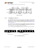
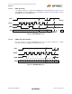
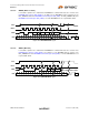
Figure 10.2 displays the various bus states of a typical I
2
C cycle.
10.2.2.2 I
2
C EEPROM Device Addressing
The I
2
C EEPROM is addressed for a read or write operation by first sending a control byte followed
by the address byte or bytes. The control byte is preceded by a start condition. The control byte and
address byte(s) are each acknowledged by the EEPROM slave. If the EEPROM slave fails to send an
acknowledge, then the sequence is aborted and the EPC_TIMEOUT bit of the EEPROM Command
Register (E2P_CMD) is set.
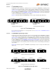
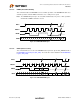
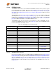
The control byte consists of a 4-bit control code, 3-bits of chip/block select and one direction bit. The
control code is 1010b. For single byte addressing EEPROMs, the chip/block select bits are used for
address bits 10, 9, and 8. For double byte addressing EEPROMs, the chip/block select bits are set
low. The direction bit is set low to indicate the address is being written.
Figure 10.3 illustrates typical I
2
C EEPROM addressing bit order for single and double byte addressing.
Figure 10.2 I
2
C Cycle
Figure 10.3 I
2
C EEPROM Addressing
EE_SDA
EE_SCL
S
Start Condition
P
Stop Condition
Data Valid
or Ack
Data Valid
or Ack
data
stable
data
can
change
data
stable
data
can
change
Sr
Re-Start
Condition
data
can
change
data
can
change
S 1 0 1 0
A
1
0
A
9
A
8
0
R/~W
Control Byte
A
7
A
6
A
5
A
4
A
3
A
2
A
1
A
0
A
C
K
A
C
K
Chip / Block
Select Bits
S 1 0 1 0 0
Control Byte
A
C
K
A
C
K
Single Byte Addressing Double Byte Addressing
A
7
A
6
A
5
A
4
A
3
A
2
A
1
A
0
A
C
K
Address Byte
Address Low
Byte
Address High
Byte
A
9
A
8
0 0 0
A
1
5
A
1
4
A
1
3
A
1
2
A
1
1
A
1
0
R/~W
Chip / Block
Select Bits