TigerSwitch 16 Intelligent bandwidth acceleration for workgroups Ethernet and Fast Ethernet Workgroup Switches ◆ Three models, each with 16 10BASE-T ports plus: ◆ Two 100BASE-TX ports ◆ Two 100BASE-FX ports ◆ One 100BASE-TX port and one 100BASE-FX port ◆ Manageable in-band via SNMP, RMON and Telnet User Guide
USER GUIDE FOR SMC’S TIGERSWITCH 16 FAMILY July 1997 Pub. # 900.185 Rev.
Information furnished by Standard Microsystems Corporation (SMC) is believed to be accurate and reliable. However, no responsibility is assumed by SMC for its use, nor for any infringements of patents or other rights of third parties which may result from its use. No license is granted by implication or otherwise under any patent or patent rights of SMC. SMC reserves the right to change specifications at any time without notice. Copyright © 1997 by Standard Microsystems Corporation Hauppauge, New York.
Limited Warranty HARDWARE: Standard Microsystems Corporation (“SMC”) warrants these TigerSwitch 16 units to be free from defects in workmanship and materials, under normal use and service, for the following length of time from the date of purchase from SMC or its Authorized Reseller: TigerSwitch 16 Units . . . . . . . . . . . . . . . . . . . . . . . . . . . . . . . . .
LIMITED WARRANTY SMC with a Return Material Authorization (RMA) number marked on the outside of the package, and sent prepaid, insured, and packaged appropriately for safe shipment. The repaired or replaced item will be shipped to Customer, at SMC’s expense, not later than thirty (30) days after receipt by SMC. WARRANTIES EXCLUSIVE: IF AN SMC PRODUCT DOES NOT OPERATE AS WARRANTED ABOVE, CUSTOMER’S SOLE REMEDY SHALL BE REPAIR, REPLACEMENT OR REFUND OF THE PURCHASE PRICE PAID, AT SMC’S OPTION.
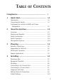
TABLE OF CONTENTS Compliances .......................................................... 1 2 3 4 v Quick Start...................................................... 1-1 Introduction ......................................................................... 1-2 Connecting the Switch......................................................... 1-3 Configuring the Switch for SNMP and Telnet Management .................................................................... 1-5 About the Switches ............
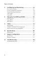
TABLE OF CONTENTS 5 Configuring and Monitoring ........................ 5-1 The Console Interface ......................................................... Typical Configuration Operations ...................................... Typical Monitoring Operations ........................................... Using Telnet ......................................................................... Using SLIP ............................................................................ 6 Managing Via SNMP and RMON ...
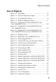
TABLE OF CONTENTS List of Figures Figure 1-1. Main Menu ....................................................... 1-4 Figure 1-2. Switch Configuration Menu ............................ 1-5 Figure 1-3. IP Configuration Menu .................................... 1-6 Figure 1-4. SNMP Configuration Menu.............................. 1-7 Figure 2-1. TigerSwitch 16 Model SMC6516TT with two 100BASE-TX Ports..................................................... 2-3 Figure 2-2.
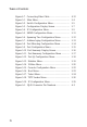
TABLE OF CONTENTS iv Figure 4-7. Connecting Fiber Cable................................... 4-12 Figure 5-1. Main Menu ....................................................... 5-4 Figure 5-2. Switch Configuration Menu ............................ 5-5 Figure 5-3. Configuration Display Screen ......................... 5-7 Figure 5-4. IP Configuration Menu .................................... 5-9 Figure 5-5. SNMP Configuration Menu.............................. 5-11 Figure 5-6.
COMPLIANCES FCC A This equipment generates, uses, and can radiate radio frequency energy and, if not installed and used in accordance with the instruction manual, may cause interference to radio communications. It has been tested and found to comply with the limits for a Class A computing device pursuant to Subpart B of Part 15 of FCC Rules, which are designed to provide reasonable protection against such interference when operated in a commercial environment.
CHAPTER 1 QUICK START Introduction . . . . . . . . . . . . . . . . . . . . . . . . . 1-2 Connecting the Switch . . . . . . . . . . . . . . . . . . 1-3 Configuring the Switch for SNMP and Telnet Management . . . . . . . . . . . . . . . . . . . . . . . . .
QUICK START Introduction SMC’s TigerSwitch™ 16 family consists of a set of three manageable Ethernet switches with Fast Ethernet connection capability. Each switch provides sixteen 10BASE-T ports for connection to Ethernet hubs, servers and workstations. Each switch also includes two ports for connection to Fast Ethernet devices. The switch, depending on the model chosen, will contain either two 100BASE-TX ports, two 100BASE-FX ports or one 100BASE-TX port and one 100BASE-FX port.
QUICK START Connecting the Switch 1. Power up the PC to be used to configure and monitor the switch out-of-band. After loading this PC with communications software, set your terminal or communications program to the following parameters: 9600, n, 8, 1 (9600 baud, no parity, 8 data bits, 1 stop bit). (See Appendix C for the Windows Terminal program parameter settings.) 2. Plug the female end of a DB-9 standard null-modem cable into the Console connector on the front panel of the switch.
QUICK START 7. Press the Esc key on the terminal or PC. The Main Menu will appear on the screen. ___________________________________________________ >>>> Main Menu <<<< 1. Switch Configuration Menu 2. Port Configuration Menu 3. Statistics Menu 4. Utilities Menu 5. Exit Menus (Password Protect) Enter Selection: ___________________________________________________ Figure 1-1.
QUICK START Configuring the Switch for SNMP and Telnet Management 8. To assign an IP address, or to have one assigned automatically, select “Switch Configuration Menu” from the Main Menu. The Switch Configuration Menu will appear. ___________________________________________________ >>>> Switch Configuration Menu <<<< 1. Configuration Summary 2. IP Configuration 3. SNMP Configuration 4. Spanning Tree Configuration 5. Address Aging Configuration 6.
QUICK START ___________________________________________________ >>>> IP Configuration Menu <<<< 1. Automatic Selection of IP Address (DHCP).. [ ON] 2. Switch IP Address.. ............. [ 170.129. 78. 28 ] 3. Default SNMP Manager IP Address.. [ 170.129. 78.208 ] 4. Default Gateway IP Address....... [ 170.129. 78. 1 ] 5. Subnet Mask...................... [ 255.255.255. 0 ] 6. SLIP Enable...................... [ 7. SLIP IP Address.................. [ 0. 0. 0. 0 ] 8. SLIP Subnet Mask.....
QUICK START nity name (up to 10 alphanumeric characters). ___________________________________________________ >>>> SNMP Configuration Menu <<<< 1. SNMP Get Community Name ( 10 characters max ).....[ public ] 2. SNMP Set Community Name ( 10 characters max ).....[ public ] 3. System Location ( 24 characters max ).. [ ] 4. System Name ( 24 characters max )...... [ ] 5. System Contact ( 24 characters max )...
CHAPTER 2 ABOUT THE SWITCHES Overview . . . . . . . . . . . . . . . . . . . . . . . . . . . Ports and Status LEDs . . . . . . . . . . . . . . . . 10BASE-T Ports . . . . . . . . . . . . . . . . . . . 100BASE-TX Port(s) . . . . . . . . . . . . . . . . 100BASE-FX Port(s) . . . . . . . . . . . . . . . . Link and Select LEDs . . . . . . . . . . . . . . . Shared Vertical LED Array and Port Select Button . . . . . . . . . . . . . . . . . Console Port . . . . . . . . . . . . . . . . . . . . . . . Reset Button . . .
ABOUT THE SWITCHES Non-volatile Parameter Storage . . . . . . . . . 2-15 Management Options . . . . Serial Console Interface Telnet . . . . . . . . . . . . . SNMP . . . . . . . . . . . . . 2-2 . . . . . . . . . . . . . . . . . . . . . . . . . . . . . . . . . . . . . . . . . . . . . . . . . . . . . . . . . . . .
ABOUT THE SWITCHES Overview SMC’s TigerSwitch 16 is a family of intelligent Ethernet workgroup switches that offers both an increase in network performance plus an economical solution for anyone planning to integrate Fast Ethernet into their Ethernet LAN. In addition to sixteen 10BASE-T ports, these switches provide two Fast Ethernet ports.
ABOUT THE SWITCHES The Fast Ethernet ports on each switch are contained in a single, dual-port replaceable module.* This modular design allows you the option of installing different types of Fast Ethernet ports, according to your changing network needs.
ABOUT THE SWITCHES Ports and Status LEDs 10BASE-T Ports The sixteen 10BASE-T ports are located on the front panel of each switch. These ports are labeled with an “x” to indicate that they have a built-in crossover.* If a 10BASE-T port is connected directly to an Ethernet server, power user or another switch, it will provide the device with a dedicated bandwidth—20 Mbps in full-duplex mode or 10 Mbps in half-duplex mode.
ABOUT THE SWITCHES When connected to a 10BASE-T device, the port will operate at 10 Mbps, providing each switch with an additional Ethernet port (two ports on the SMC6516TT). When connected to a 100BASETX device, the port will operate at the higher data rate, allowing for the easy integration of Fast Ethernet into an Ethernet LAN.
ABOUT THE SWITCHES Link and Select LEDs Each of the RJ-45 connectors on the 10BASE-T and 100BASE-TX ports has dual integrated LEDs. The left LED displays the port’s Link status. If this LED is lit (green), it indicates that the connection between the port and the attached device is good.
ABOUT THE SWITCHES Shared Vertical LED Array and Port Select Button At power-up, the shared vertical LED array displays the status of port 1. To display the status of port 2, press the Port Select button located to the right of the array. Repeated depressions of this button will cycle through all eighteen ports. Figure 2-7.
ABOUT THE SWITCHES Console Port Each switch contains a Console port on the front panel. This is an RS-232 serial port with a DB-9 connector. When connected to a PC, this port can be used to configure the switch and to monitor the switch out-of-band and in-band via Telnet. Figure 2-8. Console Port and Reset Button Reset Button The front panel of each switch contains a Reset button. This button is used to restart the switch. It has almost the same effect as powering the switch off and on again.
ABOUT THE SWITCHES Power Supply Receptacles and Status LEDs There are two power receptacles on the rear of each switch. The standard receptacle labeled “Power” is for the AC power cord. The 14-pin receptacle labeled “DC Input” is for the optional Redundant Power Unit (RPU). Figure 2-9. Power Supply Receptacles Power and RPU LEDs located on the front panel of each switch indicate the status of both the internal and redundant power supplies. These LEDs are described on the following page. Figure 2-10.
ABOUT THE SWITCHES Power Supply Status LEDs LED Condition Power Redundant Power Status Off Off No AC power Green Off Internal power supply is operating properly; redundant power supply is not present or has been disconnected Green Green Both internal and redundant power supplies are operating properly Red Green Internal power supply has failed; device is being powered by redundant power supply Red Off Redundant power supply has failed; device is being powered by internal power supply 2-11
ABOUT THE SWITCHES Features and Benefits • IEEE 802.3 and 802.
ABOUT THE SWITCHES Switch Architecture Buffered Switching Each TigerSwitch 16 unit is a “store-and-forward” device. Every packet it receives is stored in a buffer so it can be checked for validity before being forwarded to another port. In addition, the switches feature a non-blocking design that allows simultaneous wire-speed transport of multiple packets at consistently low latency.
ABOUT THE SWITCHES Spanning Tree Protocol The TigerSwitch 16 family supports the IEEE 802.1d Spanning Tree Protocol. This protocol adds a level of fault tolerance by allowing two or more redundant connections to be created between a pair of LAN segments. When there are multiple physical paths between segments, the protocol can choose a single path at any given time and disable all others. This prevents network traffic from circulating in an endless loop.
ABOUT THE SWITCHES Switch Operation Diagnostic Tests Diagnostic tests are performed whenever the switch is powered up or reset. Upon power-up, the test results are displayed on the PC attached to the Console port. During the test sequence, the switch detects whether or not the software is loaded. If it is, the Main Menu is displayed. Otherwise, the Boot Loader Menu is displayed so that new software can be downloaded. Note: Diagnostics are not displayed when the Reset Button is pressed.
ABOUT THE SWITCHES Management Options The TigerSwitch 16 family can be managed using any one of the following three methods: • out-of-band via the RS-232 console interface • in-band via Telnet • in-band via any SNMP-based network manager Serial Console Interface The switches can be managed out-of-band via the RS-232 console port. This requires a PC running a terminal application such as Windows Terminal.
ABOUT THE SWITCHES SNMP In addition, the switches can be managed in-band from a workstation using EliteView or any other SNMP-based manager. Simple Network Management Protocol (SNMP), the most popular management protocol in use today, defines the structure of information maintained on a device being managed, and the operations used to access the information. SNMP provides two levels of management security protection based on community names.
CHAPTER 3 PLANNING Benefits of Switching . . . . . . . . . . . . . . . Switched Ethernet — Multiple Simultaneous Data Streams . . . . . . . . Switched Fast Ethernet — High-Speed Data Pipes . . . . . . . . . . . . . . . . . . . . . Switching — an Evolutionary Step . . . . . . . 3-2 . . . . 3-2 . . . . 3-3 . . . . 3-3 Segmenting the Network . . . . . . . . . . . . . . . . 3-4 Client/Server . . . . . . . . . . . . . . . . . . . . . . . 3-4 Backbone Connections . . . . . . . . . . . . . . .
PLANNING Benefits of Switching Ethernet is traditionally a shared technology. Its media (network cable) is shared, so only one transmission can take place at a time. Its 10 Mbps bandwidth is shared too, so as more users are added to the network, there is less available bandwidth for each user.
PLANNING into multiple collision domains, yet cost-effective enough to allow users to dedicate bandwidth to workstations, file servers and print servers. At the desktop level, switches can replace Ethernet hubs. By providing servers and high-performance workstations with dedicated 10 Mbps LAN connections, switches boost the throughput and performance of bandwidth intensive applications, such as imaging, CAD/CAM and relational database access. At the workgroup level, switches can coexist with Ethernet hubs.
PLANNING Segmenting the Network Each port on a switch is a separate segment, so when implementing switching, you must decide how to segment the network. For desktop switching, the decision is easy, as each PC is on a separate segment. For segment switching, it is a good idea to investigate the traffic flow on the network and the interactions of the applications being used.
PLANNING Full-Duplex Operation Full duplex is a transmission method that allows a network device to transmit and receive concurrently. This mode is supported by some 10BASE-T and 100BASE-TX switches and network cards, but not by hubs or by 100BASE-T4 devices. Connecting a pair of devices that can operate in full-duplex mode eliminates collisions and effectively doubles the bandwidth of that segment. In addition, full-duplex operation can also be used to extend Fast Ethernet fiber cabling distances.
PLANNING Sample Applications Sample applications are provided below. They show how switching technology can increase the performance of a shared Ethernet Client/Server LAN without extensive network reconfiguration and changes to the infrastructure. Shared Ethernet LAN In the traditional Client/Server LAN, all the workstations and servers are connected to stackable and/or standalone hubs. As additional workgroups are added to the LAN, hubs are added to accommodate them.
PLANNING Segmented Ethernet LAN To reduce contention, the network is segmented into separate repeater groups. This enables the workstations on each segment to share the 10 Mbps bandwidth of that segment. Reducing the number of stations on each segment decreases the amount of collisions that occur as a matter of course on a conventional shared Ethernet LAN when traffic is heavy. Note that stations on the same segment can communicate only with one another; there is no communication between segments.
PLANNING Switched Ethernet LAN To enable the segments to communicate with one another, they are interconnected through a switch. Switches, like hubs, can be cascaded to interconnect additional segments. In the figure shown below, six TigerStack segments are interconnected via an 8-port Ethernet switch. The remaining two 10BASE-T ports on the switch are configured for full-duplex operation. This provides them both with 20 Mbps of bandwidth.
PLANNING Integrating Ethernet and Fast Ethernet Some Ethernet switches also have one or two Fast Ethernet ports. These ports can be used to integrate Fast Ethernet into an Ethernet network. TigerSwitch 16 Model SMC6516TT This TigerSwitch 16 model contains two 100BASE-TX ports. Each Fast Ethernet port can be connected to a Fast Ethernet hub, to a server containing a Fast Ethernet network card such as SMC’s EtherPower™ II 10/100 PCI card, or to a 100BASE-TX port on another switch.
PLANNING TigerSwitch 16 Model SMC6516TF This model contains one 100BASE-TX port and one 100BASE-FX port. The 100BASE-FX port can be used to connect the switch to a 100BASE-FX port on another switch or hub, making it part of a high-speed fiber backbone. The longer allowable run distance for fiber cable also makes the 100BASE-FX port useful for connecting to remote devices.
PLANNING TigerSwitch 16 Model SMC6516FF This model contains two 100BASE-FX ports. When configured for full-duplex operation, these 100BASE-FX ports can be connected to other devices with up to 2 km of fiber cable. This allows the user to take advantage of a significantly higher maximum cable run distance than that available for other media.
CHAPTER 4 INSTALLING Selecting a Site . . . . . . . . . . . . . . . . . . . . . . . 4-2 Equipment Checklist . . . . . . . . . . . . . . . . . . . 4-3 Package Contents . . . . . . . . . . . . . . . . . . . 4-3 Required Rack-Mounting Equipment . . . . . 4-3 Mounting . . . . . . . . . . . . . . . . . . . . . . . . . . . 4-4 Rack Mounting . . . . . . . . . . . . . . . . . . . . . 4-4 Desktop or Shelf Mounting . . . . . . . . . . . . 4-5 Connecting to the Console Port . . . . . . . . . . .
INSTALLING Selecting a Site The TigerSwitch 16 family can be installed in a standard 19-inch equipment rack or on a desktop or shelf. Be sure to follow the guidelines below when choosing a location.
INSTALLING Equipment Checklist After unpacking your switch, check the contents of the box against the packing list below to be sure you’ve received all the components. Package Contents In addition to this user guide, the package should contain: ◆ One TigerSwitch 16 switch ◆ Bracket Mounting Kit containing two brackets and four screws for attaching the brackets to the switch ◆ Four adhesive feet ◆ Appropriate power cord(s) ◆ 3.
INSTALLING Mounting A TigerSwitch 16 unit can be mounted in a standard 19-inch equipment rack or on a desktop or shelf. Mounting instructions for each type of site follow. Rack Mounting Before rack mounting the switch, pay particular attention to the following factors: ◆ Temperature: Since the temperature within a rack assembly may be higher than the ambient room temperature, check that the rack-environment temperature is within the specified operating temperature range.
INSTALLING 2. Mount the device in the rack, using four rack-mounting screws and nuts (not provided). Figure 4-2. Installing the Switch in a Rack 3. Turn to the section, “Connecting to the Console Port.” Desktop or Shelf Mounting 1. Attach the four adhesive feet to the bottom of the switch. Figure 4-3. Attaching the Adhesive Feet 2. Set the switch on a flat surface near an AC power source, making sure there are at least two inches of space on all sides for proper air flow. 3.
INSTALLING Connecting to the Console Port Each TigerSwitch 16 model contains a Console port on the front panel. This is an RS-232 serial port with a male DB-9 connector. When connected to a PC, this port can be used to: ◆ Monitor the switch out-of-band ◆ Change the default configuration settings for specific applications, for example: • Assign an IP address for Telnet and SNMP management • Set passwords for security reasons Note: Access rights default to read/write.
INSTALLING Connecting to a Power Source 1. Plug one end of the appropriate power cable (see below) into the back of the switch, and the other end into a grounded, 3-pin socket. For North American Use: Each switch is shipped with one standard AC line cord for North America that is UL and CSA approved. For International Use: The International version of the switch is shipped with AC line cords for Continental Europe and the UK.
INSTALLING Diagnostic Self-Tests When the switch is powered up, diagnostic tests are performed, and the test results are displayed on the PC attached to the Console port. ___________________________________________________ SMC TigerSwitch 16 ROM Checksum . . . . . . . . . . . . .PASSED Local RAM Test (Byte) . . . . . . . . .PASSED Local RAM Test (Quad Word) . . . . . .PASSED ___________________________________________________ Figure 4-6.
INSTALLING Making Network Connections Switches are designed to interconnect multiple segments, or collision domains. Each segment may contain a single server or workstation, or multiple workstations that are connected to a hub. An overview of the rules for both Ethernet and Fast Ethernet collision domains is provided below.
INSTALLING 100 Mbps Fast Ethernet Collision Domain SMC 3 - 2 Rule for Class II Repeaters Between any two PCs or other stations in the same 100BASE-T collision domain, there may be: • up to 3 link segments and • up to 2 Class II repeaters (hubs) SMC 2 - 1 Rule for Class I and Class II Repeaters Between any two PCs or other stations in the same 100BASE-T collision domain, there may be: • up to 2 link segments and • up to 1 Class I or Class II repeater (hub) Maximum 100BASE-T Network Diameter* Repeater Type Tw
INSTALLING Twisted-Pair Devices Each 10BASE-T and 100BASE-TX device requires an unshielded twisted-pair (UTP) cable with RJ-45 connectors at both ends. For 10BASE-TX connections, two pairs of Category 3, 4 or 5 cable are required. 100BASE-TX connections require two pairs of certified Category 5 cable. Cabling Guidelines Every twisted-pair connection must have a wiring crossover to transmit and receive data.
INSTALLING Connecting Devices Servers, workstations, hubs and other switches can be connected to the switch with a twisted-pair cable segment. This segment may be up to 100 m (328 feet) in length. Be sure to use the appropriate type of cable (either crossover or straightthrough). Use only certified Category 5 cable for the 100BASETX connection. Attach one end of the cable to an unused port on the switch, and the other end to the RJ-45 port on the other device.
INSTALLING Default Settings Each switch is set to operate as a transparent bridge using the default operating parameters. It will automatically learn the addresses of all active stations on each segment and appropriately switch traffic between its ports. To change the configuration of the switch, turn to Chapter 5.
CHAPTER 5 CONFIGURING AND MONITORING The Console Interface . . . . . . . . . . . . Using the Console Interface . . . . . . Main Menu . . . . . . . . . . . . . . . . . . Switch Configuration Menu . . . . . . Configuration Display Screen . . . . . IP Configuration Menu . . . . . . . . . SNMP Configuration Menu . . . . . . . Spanning Tree Configuration Menu Address Aging Configuration Menu Port Mirroring Configuration Menu . Port Configuration Menu . . . . . . . . Port Summary Display Screen . . . .
CONFIGURING AND MONITORING Telnet Menu . . . . . . . . . . . . . . . . . . . . . . . 5-24 Typical Configuration Operations . . . . . . . . . Setting the Password . . . . . . . . . . . . . . . . Disabling the Password . . . . . . . . . . . . . . Configuring the IP Address . . . . . . . . . . . Changing the Port Settings . . . . . . . . . . . . Configuring Address Aging . . . . . . . . . . . Configuring Spanning Tree Protocol . . . . . Returning to Factory Settings . . . . . . . . . .
CONFIGURING AND MONITORING The Console Interface Once a PC has been connected to the Console port on the front panel of the switch, it can be used to reconfigure the switch and monitor its operation out-of-band. If you have not already done so, power up the device and set the communications program to the following parameters: 9600, n, 8, 1 (9600 baud, no parity, 8 bits, 1 stop bit). Note: This interface operates at either 9600 or 19,200 baud. The default value is 9600.
CONFIGURING AND MONITORING Main Menu The Main Menu is shown below. ___________________________________________________ >>>> Main Menu <<<< 1. Switch Configuration Menu 2. Port Configuration Menu 3. Statistics Menu 4. Utilities Menu 5. Exit Menus (Password Protect) Enter Selection: ___________________________________________________ Figure 5-1. Main Menu Menu Selections Switch Configuration Menu—Displays the Switch Configuration Menu (see Figure 5-2).
CONFIGURING AND MONITORING Switch Configuration Menu The Switch Configuration Menu is accessed from the Main Menu. ___________________________________________________ >>>> Switch Configuration Menu <<<< 1. Configuration Summary 2. IP Configuration 3. SNMP Configuration 4. Spanning Tree Configuration 5. Address Aging Configuration 6. Port Mirroring Configuration To Exit Menu Enter Selection: ___________________________________________________ Figure 5-2.
CONFIGURING AND MONITORING Address Aging Configuration—Displays the Address Aging Configuration Menu (see Figure 5-7). This menu allows you to turn address aging on and off, and to set the aging time. Port Mirroring Configuration—Displays the Port Mirroring Configuration Menu (see Figure 5-8). This menu allows you to turn port mirroring on and off, and to select both the port to be mirrored and the port to be used for monitoring.
CONFIGURING AND MONITORING Configuration Display Screen The Configuration Display Screen is accessed from the Switch Configuration Menu. ___________________________________________________ >>>> Configuration Display <<<< Number of Ports............................. [ 18 ] Port 1 MAC Address................ [ 00800F80000A ] Switch IP Address.............. [ 0. 0. 0. 0 ] Default SNMP Manager IP Address [ 0. 0. 0. 0 ] Default Gateway IP Address..... [ 0. 0. 0. 0 ] Subnet Mask.................
CONFIGURING AND MONITORING Default SNMP Manager IP Address—Displays the address of the default SNMP manager. Default Gateway IP Address—Displays the default gateway IP address to which the unit sends IP packets destined for a different subnet. Subnet Mask—Displays the IP subnet mask that corresponds to the assigned IP address. SLIP Enable—Indicates whether SLIP is enabled or disabled. SLIP is not enabled until after the switch has been reset. SLIP IP Address—Displays the SLIP IP address.
CONFIGURING AND MONITORING IP Configuration Menu The IP Configuration Menu is accessed from the Switch Configuration Menu. ___________________________________________________ >>>> IP Configuration Menu <<<< 1. Automatic Selection of IP address (DHCP).. [ ON] 2. Switch IP Address........... ..... [ 170.129. 78. 28 ] 3. Default SNMP Manager IP Address... [ 170.129. 78.208 ] 4. Default Gateway IP Address........ [ 170.129. 78. 1 ] 5. Subnet Mask....................... [ 255.255.255. 0 ] 6. SLIP Enable.
CONFIGURING AND MONITORING packets destined for a different subnet. Subnet Mask—Allows you to enter the IP subnet mask that corresponds to the assigned IP address. SLIP Enable—Allows you to enable or disable SLIP. After setting this field to “enable”, the swtich must be reset to actually enable SLIP. SLIP IP Address—Allows you to enter the SLIP IP address. Note: This address must be different from the Switch IP address. The Host Address can be the same,.but the network number must be different.
CONFIGURING AND MONITORING SNMP Configuration Menu The SNMP Configuration Menu is accessed from the Switch Configuration Menu. ___________________________________________________ >>>> SNMP Configuration Menu <<<< 1. SNMP Get Community Name ( 10 characters max ).. [ public ] 2. SNMP Set Community Name ( 10 characters max ).. [ public ] 3. System Location ( 24 characters max ).. [ ] 4. System Name ( 24 characters max )...... [ ] 5. System Contact ( 24 characters max )...
CONFIGURING AND MONITORING Spanning Tree Configuration Menu The Spanning Tree Configuration Menu is accessed from the Switch Configuration Menu. ___________________________________________________ >>>> Spanning Tree Configuration Menu <<<< 1. Spanning Tree Protocol...................... [ On ] 2. Switch Priority (0-65535)................... [ 32768 ] 3. Switch Maximum Age (6-40 seconds)........... [ 20 ] 4. Switch Hello Time (1-10 second)............. [ 2 ] 5.
CONFIGURING AND MONITORING Address Aging Configuration Menu The Address Aging Configuration Menu is accessed from the Switch Configuration Menu. ___________________________________________________ >>>> Address Aging Configuration Menu <<<< 1. Address Aging........................ [ On ] 2. Address Aging Time (120-1000000 sec). [ 300 ] To Exit Menu Enter Selection: ___________________________________________________ Figure 5-7.
CONFIGURING AND MONITORING Port Mirroring Configuration Menu The Port Mirroring Configuration Menu is accessed from the Switch Configuration Menu. ___________________________________________________ >>>> Port Mirroring Configuration Menu <<<< 1. Port Mirroring............................... [ Off ] 2. Mirror Port.................................. [ 2 ] 3. Monitor Port.................................
CONFIGURING AND MONITORING Port Configuration Menu The Port Configuration Menu is accessed from the Main Menu. ___________________________________________________ >>>> Port Configuration Menu <<<< 1. Port Summary 2. Address Tables 3. Port Settings To Exit Menu Enter Selection: ___________________________________________________ Figure 5-9. Port Configuration Menu Menu Selections Port Summary—Displays the Port Summary Display Screen (see Figure 5-10).
CONFIGURING AND MONITORING Port Summary Display Screen The Port Summary Display Screen is accessed from the Port Configuration Menu by selecting “Port Summary.” All the fields on this screen are read-only.
CONFIGURING AND MONITORING Port Summary Configuration Menu The Port Summary Configuration Menu is accessed from the Port Configuration Menu by selecting “Port Settings.” In addition to displaying the settings for all ports, the menu allows you to change the settings for a particular port (see Figure 5-12).
CONFIGURING AND MONITORING Port [x] Configuration Menu The Port [x] Configuration Menu is accessed from the Port Summary Configuration Menu by entering the number of a port whose settings are to be edited. ___________________________________________________>>>> Port [x] Configuration Menu <<<< 1. Port Status.............................. [ Enabled ] 2. Port Path Cost........................... [ 100 ] 3. Port Priority............................ [ 128 ] 4. Port Duplex Mode.........................
CONFIGURING AND MONITORING Statistics Menu The Statistics Menu is accessed from the Main Menu. The selections on this menu are standard MIB II read-only statistics (refer to RFC 1213). ___________________________________________________ >>>> Statistics Menu <<<< 1. Display System Statistics 2. Display IF Statistics 3. Display IP AT Table 4. Display IP Statistics 5. Display ICMP Statistics 6. Display UDP Statistics 7.
CONFIGURING AND MONITORING Utilities Menu The Utilities Menu is accessed from the Main Menu. ___________________________________________________ >>>> Utilities Menu <<<< 1. Console Configuration 2. Display/Clear Error Log 3. Password Configuration 4. Reset To Factory Defaults 5. Initiate Software Download 6. Establish Telnet Session 7. Initialize Modem To Exit Menu Enter Selection: ___________________________________________________ Figure 5-14.
CONFIGURING AND MONITORING Reset To Factory Defaults—Allows you to reset the system to factory defaults. This procedure only resets the switch parameters. You are prompted with the message: “Reset to factory defaults ? (Y/N).” Initiate Software Download—Displays the Boot Menu (see Figure 5-16). This menu allows you to initiate a software download. (See page 5-29 of this guide for a fully detailed discussion of this option.) Establish Telnet Session—Displays the Telnet Menu (see Figure 5-17).
CONFIGURING AND MONITORING Console Configuration Menu The Console Configuration Menu is accessed from the Utilities Menu by selecting “Console Configuration.” ___________________________________________________ >>>> Console Configuration Menu <<<< 1. Baud Rate...............................[ 9600 ] 2. Accept New Settings To Exit Menu Enter Selection: ___________________________________________________ Figure 5-15.
CONFIGURING AND MONITORING Boot Menu The Boot Menu is accessed from the Utilities Menu by selecting “Initiate Software Download.” ___________________________________________________ >>>> TigerSwitch 16 Boot Menu <<<< Boot Code Version XX.XX 1. Software Download via RS-232 Interface 2. Software Download via TFTP 3. Start System To Exit Menu Enter Selection: ___________________________________________________ Figure 5-16.
CONFIGURING AND MONITORING Telnet Menu The Telnet Menu is accessed from the Utilities Menu by selecting “Establish Telnet Session.” ___________________________________________________ >>>> Telnet Menu <<<< 1. Configure Telnet Server IP Address.[ 0. 0. 0. 0] 2. Initiate Telnet Session To Exit Menu Enter Selection: ___________________________________________________ Figure 5-17.
CONFIGURING AND MONITORING Typical Configuration Operations Instructions for performing some typical configuration operations via the console interface are provided below. Setting the Password Setting a password prevents unauthorized users from reconfiguring the switch. At the factory, the password is not enabled so that you may access the console interface and set the first password. To set (or change) a password for the Console port or for inbound Telnet: 1.
CONFIGURING AND MONITORING Disabling the Password To disable password protection for the Console port or for inbound Telnet: 1. At the Main Menu, type 4 to display the Utilities Menu. 2. At the Utilities Menu, type 3. The system prompts: “Enter New Password.” 3. Type in “SMC.” 4. The system prompts: “Re-enter New Password.” Type the “SMC” password a second time. Configuring the IP Address To assign an IP address to the switch: 1. At the Main Menu, type 1 to display the Switch Configuration Menu. 2.
CONFIGURING AND MONITORING Changing the Port Settings To change any of the port settings on the switch: 1. At the Main Menu, type 2 to display the Port Configuration Menu. 2. At the Port Configuration Menu, type 3 to display the Port Summary Configuration Menu. 3. Type the number of the port whose settings you wish to change. The Port [x] Configuration Menu is displayed. 4. Type the number of the parameter you wish to change. 5. The system then prompts you to enter the new value and to confirm your change.
CONFIGURING AND MONITORING Configuring Spanning Tree Protocol The Spanning Tree Algorithm requires certain parameter settings The default settings should be acceptable in most networks. If you need to change the defaults, proceed as follows: 1. At the Main Menu, type 1 to display the Switch Configuration Menu. 2. At the Switch Configuration Menu, type 4 to display the Spanning Tree Configuration Menu. 3. Type the number of the parameter you want to change. The system prompts you to enter the new value. 4.
CONFIGURING AND MONITORING Downloading New Software New software may be downloaded to the switch via TFTP or the RS-232 Console port. Downloading via TFTP is substantially faster. Serial downloading (via the Console port) may take in excess of half an hour or more. When downloading via the RS-232 port, the PC connected to the Console port must be running a terminal emulation application. Be sure that the ASCII transfer parameters are set for maximum throughput.
CONFIGURING AND MONITORING 7. Type 2, and you are prompted to enter the IP address of the server where the file is located. Enter the IP address. 8. Type 3, and you are prompted to enter the IP address of the switch. Enter the IP address. 9. If desired, you may select 7 to ping the server and test its status before beginning the download. 10. Type 6 to begin the TFTP download. A warning message is displayed followed by the prompt: “START TFTP DOWNLOAD? (Y/N).” 11. Type Y to start the download.
CONFIGURING AND MONITORING Downloading Software via RS-232 Port 1. Attach your terminal to the RS-232 port and access the Main Menu. 2. At the Main Menu, type 4 to display the Utilities Menu. 3. At the Utilities Menu, type 5 to display the Boot Menu. 4. Type 1 to initiate a software download. The system prompts with a warning and the message: “DO YOU WANT TO CONTINUE? (Y/N).” Note: If you type Y, all network traffic through the switch will be disabled. 5. Type 1 to begin the download.
CONFIGURING AND MONITORING Typical Monitoring Operations Instructions for performing some typical monitoring operations via the console interface are provided below. Displaying the Current Configuration To display information about the current configuration of the switch: 1. At the Main Menu, type 1 to display the Switch Configuration Menu. 2. At the Switch Configuration Menu, type 1 to display the Configuration Display Screen. 3.
CONFIGURING AND MONITORING Displaying Spanning Tree Parameters To display the current Spanning Tree Parameters: 1. At the Main Menu, type 1 to display the Switch Configuration Menu. 2. At the Switch Configuration Menu, type 4 to display the Spanning Tree Configuration Menu. 3. At the Spanning Tree Configuration Menu, type 6 to display the current Spanning Tree Parameters. 4. After viewing the information, press any key to return to the Spanning Tree Configuration Menu.
CONFIGURING AND MONITORING Using Telnet The console interface can also be used to configure and monitor the switch in band via Telnet. Telnet is a common terminal emulation application used in TCP/IP networks for remote terminal access to computer devices. Before using Telnet, an IP address must be assigned to the switch. This IP address must be set out-of-band using the console interface.
CONFIGURING AND MONITORING Using SLIP SLIP (Serial Line Internet Protocol) is a simple protocol that is used solely for encapsulating and framing IP packets that are being transmitted over serial lines. To set up for out-of-band management via SNMP using SLIP, proceed as follows: 1. From the Main Menu, type 1 to select the Switch Configuration Menu. 2. From the Switch Configuration Menu, type 2 to select the IP Configuration Menu.
CONFIGURING AND MONITORING 5. Connect one end of an RS-232 modem cable to the switch and the other end to a modem. Plug the modem into the phone jack. Also, be sure the modem is set to Auto-answer. 6. Configure the remote workstation to use the SLIP protocol. 7. Attach the remote workstation to a modem using an RS-232 modem cable. Plug the modem into the phone jack. 8. From the remote workstation, dial the phone number of the modem connected to the switch. Verify that you are able to auto-connect.
and the operating mode (half or full duplex).
CHAPTER 6 MANAGING VIA SNMP AND RMON SNMP Protocol . . . . . . . . . . . . . . . . . . . . . . . 6-2 Using RMON . . . . . . . . . . . . . . . . . . . . . . . . . 6-3 MIB Objects . . . . . . . . . . . . . . . . . . . . . . . . .
MANAGING VIA SNMP AND RMON SNMP Protocol SNMP (Simple Network Management Protocol) is a communication protocol designed specifically for the purpose of managing devices or other elements on a network. Network equipment commonly managed with SNMP includes hubs, switches, bridges, routers and host computers. SNMP is typically used to configure these devices for proper operation in a network environment, as well as monitor them to evaluate performance and detect potential problems.
MANAGING VIA SNMP AND RMON ware, and result in a response by the agent. The third operation type, the TRAP, allows the agent to send an unsolicited message to the manager. This operation is typically used as an alert to a potential problem, or a change in device status. Using RMON The switch offers an RMON subset contained within the basic system management. The objects supported are some of the most pertinent objects within RMON and include the Event, Alarm, Statistics and History groups.
MANAGING VIA SNMP AND RMON The main standard MIB, referred to as MIB II, provides an overall view of the managed agent and is supported, at least in part, by all SNMP agents. In addition, proprietary MIB extensions are defined by commercial vendors for managing device-specific functions of their products.
APPENDIX A CABLES Specifications . . . . . . . . . . . . . . . . . . . . . . . . A-2 10BASE-T/100BASE-TX Pin Assignments . . . . A-3 Straight-Through Wiring . . . . . . . . . . . . . . . A-4 Crossover Wiring . . . . . . . . . . . . . . . . . . . . A-4 Serial Console Port Pin Assignments . . . . . . . .
CABLES Specifications Twisted-Pair Cable Cable Type 100 ohm UTP Technology Category Connector 10BASE-T 3, 4, 5 male 8-pin 100BASE-TX 5 certified RJ-45 22 - 26 AWG 0.4 - 0.6 mm Fiber Cable Cable Type Technology Connector 62.
CABLES 10BASE-T/100BASE-TX Pin Assignments Caution: Regulations regarding the connection of equipment to telephone networks vary from country to country. Check with your local telephone network supplier before using existing telephone wiring. An Ethernet twisted-pair link segment requires two pairs of wires. Each wire pair is identified by two different colors. For example, one wire might be green and the other, green with white stripes.
CABLES Straight-Through Wiring If the twisted-pair link segment is to join two ports and only one of the ports has an internal crossover, the two pairs of wires must be straight-through.
CABLES Serial Console Port Pin Assignments Any cable connected to the Console port must be shielded to comply with FCC emissions regulations and with requirements of other regulatory agencies in various parts of the world.
APPENDIX B SPECIFICATIONS Specifications . . . . . All Models . . . . . . Model SMC6516TT Model SMC6516FF Model SMC6516TF ... ... .. ... ... . . . . . . . . . . . . . . . . . . . . . . . . . . . . . . . . . . . . . . . . . . . . . . . . . . . . . . . . . . . . . . . . . . . . . . . . . . . . . . . .
SPECIFICATIONS Specifications All Models Buffer Architecture Central memory, dynamic allocation 3 Mbytes DRAM Architecture Bus Latency 12 µs MAC Addresses 8,192 total, dynamically allocated among all ports Forwarding/Filtering/Learning Rates Full line-rate for 10 Mbps ports Full line-rate for 100 Mbps ports In-band Management Telnet or any SNMP manager Out-of-band Management RS-232 Console port Software Loading TFTP in-band RS-232 out-of-band Network Interface for 10BASE-T ports RJ-45 connector, fixed cros
SPECIFICATIONS LEDs Power Redundant Power Port Status - 1 per port Port Select - 1 per port Shared vertical array Receive Collision Full Duplex 100 Mbps Buttons Port Select Reset Size 16.9 in.W x 9.2 in. D x 1.7 in. H (42.9 cm x 23.4 cm x 4.3 cm) Temperature Operating 32° to 131° F (0° to 50° C) Storage -13° to 185° F (-25° to 85° C) Humidity 10% to 90%, non-condensing Power Supply Universal AC input 120 to 240 VAC, 50 to 60 Hz Power Consumption 84 W maximum Standards IEEE 802.3 Ethernet IEEE 802.
SPECIFICATIONS Compliances CE marking Safety UL 1950 CSA 22.2 No. 950 EN 60950 Immunity IEC 801-2.3.4 EN 50082-1 Emissions FCC Class A CDOC Class A EN 55022 (CISPR 22) Class A VCCI Class 1 Warranty Three years Model SMC6516TT Ports 16 10BASE-T 2 100BASE-TX with Auto-Negotiation Weight 10.0 lbs. (4.54 kg) Model SMC6516FF Ports 16 10BASE-T 2 100BASE-FX with full-duplex support Network Interface for 100BASE-FX ports SC connector Fiber cable, 62.5/125 micron Weight 10.0 lbs. (4.
SPECIFICATIONS Model SMC6516TF Ports 16 10BASE-T 1 100BASE-TX with Auto-Negotiation 1 100BASE-FX with full-duplex support Weight 10.0 lbs. (4.
APPENDIX C SAMPLE CONFIGURATION Introduction . . . . . . . . . . . . . . . . . . . . . . . . .C-2 Windows Terminal . . . . . . . . . . . . . . . . . . . .
SAMPLE CONFIGURATION Introduction This appendix contains instructions for using the Windows Terminal communication application to connect to any one of the TigerSwitch 16 models via the out-of-band Console port. Make sure that the ASCII transfer parameters are set as follows: • 8 bits • no parity • 1 stop bit • 9600 (default) or 19.2 baud • no flow control In addition, be sure that: • All data flow control parameters are turned OFF.
SAMPLE CONFIGURATION Windows Terminal If you are using the Windows program called Terminal, you can use the defaults except for the following: Menu Parameter and Setting Settings Terminal Emulation TTY (Generic) - ON Settings Text Transfers Line at a time - ON Delay Between Lines - 0 Settings Communications Data Bits - 8 Parity - None Stop Bits - 1 Settings Terminal Preferences Use Function, Arrow and CTRL keys for Windows - OFF (no x in the box) Transfers Send Text File Append LF - OFF (no x in
APPENDIX D TROUBLESHOOTING Troubleshooting Chart . . . . . . . . . . . . . . . . . .
TROUBLESHOOTING Troubleshooting Chart Symptom Action Power LED is Off No AC power. Check connections between the switch, the power cord and the wall outlet. Contact SMC Tech Support. Power LED is Red Internal or redundant power supply has failed or is disconnected. Power LED is Green, Internal power supply is operating Redundant Power LED properly; redundant power supply is is Off not present or has been disconnected.
FOR TECHNICAL SUPPORT, CALL: From U.S.A. and Canada (8:30 AM - 8:00 PM Eastern Time) (800) SMC-4-YOU; (516) 435-6250; (516) 434-9314 (Fax) From Europe (8:00 AM - 5:30 PM UK Greenwich Mean Time) 44 (0) 1344-420068; 44 (0) 1344-418835 (Fax) Bulletin Board Services (BBS) Modem settings: 9600,8,n,1 New York: (516) 434-3162 (connect speed up to 14,400) Germany: 49 (0) (89) 92861-240 France: 33 (1) 39.73.57.00 United Kingdom: 44 (0) 1344 418838 INTERNET address is: techsupport@smc.