USB20H04 4-Port USB 2.0 Hub Controller Datasheet Product Features General Features Compliant with USB 2.
4-Port USB 2.0 Hub Controller Datasheet 80 ARKAY DRIVE, HAUPPAUGE, NY 11788 (631) 435-6000, FAX (631) 273-3123 Copyright © 2007 SMSC or its subsidiaries. All rights reserved. Circuit diagrams and other information relating to SMSC products are included as a means of illustrating typical applications. Consequently, complete information sufficient for construction purposes is not necessarily given.
4-Port USB 2.0 Controller Datasheet Table of Contents Chapter 1 1.1 1.2 1.3 General Description ............................................................................................................. 5 Applications ......................................................................................................................................... 5 OEM Selectable Features ...................................................................................................................
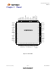
-Port USB 2.0 Hub Controller Datasheet List of Figures Figure 2.1 - Block Diagram.............................................................................................................................................7 Figure 3.1– 64 Pin TQFP ...............................................................................................................................................8 Figure 8.1 - 2-Wire EEPROM Interface.................................................................................
4-Port USB 2.0 Controller Datasheet Chapter 1 General Description The USB20H04 four-port hub controller is fully compliant with the USB 2.0 Specification and does not require firmware development. When connected to a high-speed host, the four downstream facing ports can operate at low-speed (1.5Mb/s), full-speed (12Mb/s), or high-speed (480Mb/s). As required by the USB 2.0 Specification, the USB20H04 is fully backward compatible with legacy full-speed hosts.
4-Port USB 2.0 Hub Controller Datasheet 1.2 OEM Selectable Features The 4-Port Hub supports several OEM selectable features: 1.3 Operation as a bus-powered, self-powered or dynamic-powered hub. (When configured for dynamic operation, the controller automatically switches to bus-powered mode if a local power source is unavailable). Configure downstream facing port power switching on an individual or ganged basis.
4-Port USB 2.
4-Port USB 2.
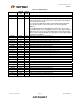
4-Port USB 2.0 Controller Datasheet Chapter 4 4.1 Interface Signal Definition Pin Descriptions Table 4.1 - System Interface Signals RESET_N BUFFER TYPE IS SELF_PWR I TEST_P0 TEST_P1 TEST_P2 TEST_P3 ATEST IPD IPD IPD IPD AO NAME ACTIVE DESCRIPTION LEVEL Low Chip Reset. The minimum active low pulse is 100ns. See section 8.4 for a complete description of operation following a reset. Self-power Detect.
4-Port USB 2.0 Hub Controller Datasheet Table 4.3 - USB I/O Signals NAME USBDP0 USBDM0 VBUSDET BUFFER TYPE IO-U IO-U IO8 ACTIVE DESCRIPTION LEVEL N/A Upstream USB Positive Data Pin. N/A Upstream USB Negative Data Pin. N/A Detects state of upstream VBUS power. When designing a detachable hub, this pin must be connected to the VBUS power pin of the USB port that is upstream of the hub. For self-powered applications with a permanently attached upstream host, this pin must be connected to either 3.3V or 5.
4-Port USB 2.0 Controller Datasheet Table 4.4 - Biasing and Clock Oscillator Signals RBIAS BUFFER TYPE I-R XTAL1/CLKIN ICLKx XTAL2 OCLKx N/A External crystal. 24MHz crystal. Not connected when using an external clock. CLKIN_EN I High Clock Input Enable. When high, an external CMOS clock drives XTAL1. NAME ACTIVE DESCRIPTION LEVEL N/A External 1% bias resistor. Requires a 12KΩ resistor to ground. Used for setting HS transmit current level and on-chip termination impedance.
4-Port USB 2.0 Hub Controller Datasheet Chapter 5 Limiting Values Table 5.1 - Absolute Maximum Ratings (In accordance with the Absolute Maximum Rating system (IEC 60134) PARAMETER 1.8V Supply Voltage (VDD1.8 and VDDA1.8) 3.3V Supply Voltage (VDD3.3 and VDDA3.3) Voltage on any I/O pin Voltage on XTAL1/CLKIN and XTAL2 Storage Temperature SYMBOL VDD1.8 CONDITIONS VDD3.3 TSTG MIN -0.5 TYP MAX 2.5 UNITS V -0.5 4.0 V -0.3 -0.3 5.5 3.6 V V -40 +125 oC Table 5.
4-Port USB 2.0 Controller Datasheet Chapter 6 Electrical Characteristics Table 6.1 - Electrical Characteristics: Supply Pins (VDD1.8 =1.74 to 2.0V; VDD3.3 =3.0 to 3.6V; VSS = 0V; TA = 0 oC to +70oC; unless otherwise specified.) PARAMETER Suspend State 1 Port Low-Speed/Full-Speed 1 Port High-Speed 2 Ports Low-Speed/Full-Speed 2 Ports High-Speed 3 Ports Low-Speed/Full-Speed 3 Ports High-Speed 4 Ports Low-Speed/Full-Speed 4 Ports High-Speed Unconfigured Enumerated State SYMBOL ICC1.8SUS ICC3.3SUS ICC1.
4-Port USB 2.0 Hub Controller Datasheet PARAMETER I, IPD, IPU Input Buffer SYMBOL COMMENTS MIN TYP MAX UNITS Low Input Level VILI TTL Levels 0.8 V High Input Level VIHI TTL Levels 2.0 Low Input Leakage IIL VIN = 0 -10 +10 uA High Input Leakage ICLK Input Buffer IIH VIN = VDD3.3 -10 +10 uA Low Input Level VILCK TTL Levels 0.8 V High Input Level VIHCK TTL Levels Hysteresis VHYSC V V 2.0 50 100 mV 0.8 V O8 and IO8 Buffer Low Output Level VOL IOL = 8 mA @ VDD3.
4-Port USB 2.0 Controller Datasheet Table 6.4 - DC Electrical Characteristics: Analog I/O Pins (DP/DM) (VDD1.8 =1.74 to 2.0V; VDD3.3 =3.0 to 3.6V; VSS = 0V; TA = 0 oC to +70oC; unless otherwise specified.
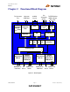
4-Port USB 2.0 Hub Controller Datasheet Chapter 7 Functional Overview Figure 2.1 shows the functional block diagram of the USB 2.0 Hub Controller. Each of the functions is described in detail below. 7.1 Bus-Power Detect The VBUSDET pin on the USB20H04 monitors the state of the upstream VBUS signal and will not pull-up the DP0 resistor if VBUS is not active. If VBUS goes from an active to an inactive state (not powered), the USB20H04 will remove power from the DP0 pull-up resistor within 10 seconds.
4-Port USB 2.0 Controller Datasheet 7.5 Serial Interface External configuration data is loaded via the serial interface. The serial interface appears as either an SMBus slave, or an I2C memory interface. 7.5.1 SMBus Slave The USB20H04 conforms to voltage, power, and timing specifications as set forth in the SMBus 1.0 Specification for Slave-Only devices. The SMBus interface shares the same pins as the EEPROM interface.
4-Port USB 2.0 Hub Controller Datasheet 7.9 Transaction Translator (TT) The transaction translator supports full-speed and low-speed devices attached to downstream ports in the high-speed environment. To provide the highest level of performance, the USB20H04 Hub provides one Transaction Translator (TT) per port (defined as multiple-TT). 7.10 Port Controller The port controller provides status and control of individual downstream ports.
4-Port USB 2.0 Controller Datasheet Each port’s indicator must be located in a position that obviously associates the indicator with the port. The color and state of the LED is used to provide status information to the user. Two different modes of operation are supported for the port indicators: automatic mode and manual mode. The USB20H04 defaults to automatic mode upon power-up. In automatic mode, the USB20H04 controls the color of the indicator LED as described in Table 7.
4-Port USB 2.0 Hub Controller Datasheet Chapter 8 Implementation Notes The following sections consist of select functional explanations to aid in implementing the Hub Controller into a system. 8.1 Configuration Implementations The USB20H04 is normally configured by an external EEPROM connected directly to the serial interface. Typical circuit diagrams are shown below.
4-Port USB 2.0 Controller Datasheet 8.1.2 Internal Default Configuration The internal default configuration is enabled when SMB_SEL_N is high and CS/EE_SEL is low on the rising edge of RESET_N. If SELF_PWR is low, then the bus-powered default settings are loaded. VDD3.3 USB20H04 Bus/Self Power Select 0=Bus-Power 1=Self-Power SMB_SEL_N CS/EE_SEL SELF_PWR SCK/SCL SD/SDA 1k Figure 8.2 - Internal Default Mode 8.
4-Port USB 2.0 Hub Controller Datasheet Detailed definition of the bits used to program the OEM values are given in Table 8.2 through Table 8.5. Table 8.2 - Address 6; Config_Byte_3 BIT 7 FIELD NAME Self-/Bus-Power 6 Port Indicators 5 High-Speed Disable 4 Multiple TT Support 3 EOP Disable 2 Current Sensing 1 Power Switching 0 Compound Device DESCRIPTION Selects either self-powered or bus-powered operation: 0: Self-powered operation. 1: Bus-powered operation.
4-Port USB 2.0 Controller Datasheet BIT 3:0 FIELD NAME Port Non-Active DESCRIPTION Selects which ports are active. A one indicates that the port is non-active: Bit 3: Port 4 is non-active. Bit 2: Port 3 is non-active. Bit 1: Port 2 is non-active. Bit 0: Port 1 is non-active. All zeroes sets all ports active. Note: Active ports must be contiguous, and must start with port number 1. Table 8.
4-Port USB 2.0 Hub Controller Datasheet Table 8.6 - Default Configuration Values REGISTER ADDRESS REGISTER NAME SELF-POWERED DEFAULT (HEX) BUS-POWERED DEFAULT (HEX) 04 24 ** 00 00 00 58 00 05 00 00 80 04 24 ** 00 00 00 98 08 05 64 64 80 01h VID MSB 02h VID LSB 03h PID MSB 04h PID LSB 05h DID MSB 06h DID LSB 07h Config Data Byte 3 08h Config Data Byte 2 09h Config Data Byte 1 0Ah Max Power 0Bh Hub Controller Max Current 0Ch Power-on Time ** The default PID value is dependent on the silicon revision.
4-Port USB 2.0 Controller Datasheet 8.4.1.1 SMBus Configuration Timing SCK/SCL t1 t3 t2 t4 RESET_N GND Hardware Reset Asserted CS/EE_SEL & SMB_SEL_N strapping options read First External SCK/SCL Activity Configuration Finished Hub Function Enable Figure 8.3 - Timing for Configuration from SMBus Table 8.
4-Port USB 2.0 Hub Controller Datasheet 8.4.1.2 EEPROM Configuration Timing SCK/SCL t1 t2 t3 t4 RESET_N GND Hardware Reset Asserted First Clock Rising Edge CS/EE_SEL & SMB_SEL_N strapping options read Configuration Finished Hub Function Enable Figure 8.4 - Timing to Complete Configuration from EEPROM Table 8.
4-Port USB 2.0 Controller Datasheet 8.4.2 USB Reset When the upstream host signals a reset, the USB20H04 does the following: Note: The USB20H04 does not propagate the upstream USB Reset to downstream devices! 1. Sets default address to 0 2. Sets configuration to: un-configured 3. Negates VBUSx_N (where x stands for the port number) to all downstream ports. 4. Clears all TT buffers. 5. Moves device from suspended to active (if suspended). 6. Complies with Section 11.10 of the USB 2.
4-Port USB 2.0 Hub Controller Datasheet Chapter 9 Hub Descriptors The USB20H04 will not electrically attach to the USB until after it has loaded valid data for all user-defined descriptor fields. A default configuration is present immediately after RESET_N negation. User defined configuration values can be loaded from either an external microcontroller or an external EEPROM. A hub returns different descriptors based on whether it is operating at high-speed or full-/low-speed.
4-Port USB 2.0 Controller Datasheet Table 9.3 - Standard Configuration Descriptor OFFSET FULL SPEED HIGH SPEED 0 09h 09h bLength 1 02h 02h bDescriptorType FIELD NAME DESCRIPTION Size of this descriptor in bytes CONFIGURATION Descriptor Type Total length of data returned for this configuration 2,3 yyyyh yyyyh wTotalLength yyyyh = 0019h if OTG support is disabled. yyyyh = 001Ch if OTG support is enabled.
4-Port USB 2.0 Hub Controller Datasheet OFFSET FULL SPEED HIGH SPEED FIELD NAME 4 01h 01h** bNumInterfaces 5 01h 01h bConfigurationValue 6 00h 00h iConfiguration 7 8 user/ user/ signal signal (Bitmap) (Bitmap) user (mA) user (mA) DESCRIPTION Number of interfaces supported by this configuration Value to use to select configuration.
4-Port USB 2.0 Controller Datasheet Table 9.
4-Port USB 2.0 Hub Controller Datasheet OFFSET 6 FIELD NAME HubContrCurrent VALUE user 7 DeviceRemovable user 8 PortPwrCtrlMask FFh Revision 1.63 (03-30-07) DESCRIPTION Maximum current requirements of the hub controller electronics in mA. Derived from OEM value. Indicates if port has a removable device attached. Derived from OEM value. Field for backwards USB 1.0 compatibility.
4-Port USB 2.0 Controller Datasheet Chapter 10 Application Diagrams The highly-integrated USB20H04 Hub Controller is complemented with a minimal number of external components to create a complete four-port Hi-Speed USB hub application. Figure 10.1 illustrates one possible hardware configuration, but is not a complete schematic. This block diagram shows a self-powered hub with individual over-current protection and power switching on each downstream port.
4-Port USB 2.0 Hub Controller Datasheet Downstream VBUS Power Source USB Type A Connector Power Switch OC Sense USB20H04 (Port 1) VBUS1_N IN EN OC OUT VBUS D+ VDD3.3 OCS1_N DUSBDP1 USBDM1 AM1_N Amber Indicator GR1_N Green Indicator Figure 10.2 - USB Downstream Port Connection Revision 1.
4-Port USB 2.0 Controller Datasheet Chapter 11 Package Outline Figure 11.1 - 64 Pin TQFP Package Outline, 10 x 10 x 1.4 Body, 2 MM Footprint Table 11.1 - 64 Pin TQFP Package Parameters A A1 A2 D D1 E E1 H L L1 e θ W R1 R2 ccc MIN ~ 0.05 1.35 11.80 9.80 11.80 9.80 0.09 0.45 ~ o 0 0.17 0.08 0.08 ~ NOMINAL ~ ~ ~ ~ ~ ~ ~ ~ 0.60 1.00 0.50 Basic ~ 0.22 ~ ~ ~ MAX 1.60 0.15 1.45 12.20 10.20 12.20 10.20 0.20 0.