USB2502 2-Port USB 2.0 Hub Controller PRODUCT FEATURES Datasheet Integrated USB 2.0 Compatible 2-Port Hub — High-Speed (480Mbits/s), Full-Speed (12Mbits/s) and Low-Speed (1.5Mbits/s) compatible — Full power management with ganged power control — Detects Bus-Power/Self-Power source and changes mode automatically Complete USB Specification 2.0 Compatibility VID/PID/DID, and Port Configuration for Hub via: — Includes USB 2.
-Port USB 2.0 Hub Controller Datasheet ORDER NUMBERS: USB2502-AEZG FOR 36 PIN LEAD-FREE ROHS COMPLIANT QFN PACKAGE; USB2502-HT FOR 48 PIN LEADFREE ROHS COMPLIANT TQFP PACKAGE 80 ARKAY DRIVE, HAUPPAUGE, NY 11788 (631) 435-6000, FAX (631) 273-3123 Copyright © 2007 SMSC or its subsidiaries. All rights reserved. Circuit diagrams and other information relating to SMSC products are included as a means of illustrating typical applications.
2-Port USB 2.0 Hub Controller Datasheet Table of Contents Chapter 1 General Description . . . . . . . . . . . . . . . . . . . . . . . . . . . . . . . . . . . . . . . . . . . . . . . . . 6 1.1 OEM Selectable Features. . . . . . . . . . . . . . . . . . . . . . . . . . . . . . . . . . . . . . . . . . . . . . . . . . . . . . . . . 6 Chapter 2 Pin Table 2-Port . . . . . . . . . . . . . . . . . . . . . . . . . . . . . . . . . . . . . . . . . . . . . . . . . . . . 7 Chapter 3 Pin Configuration 2-Port Hub . . .
2-Port USB 2.0 Hub Controller Datasheet List of Tables Table 2.1 Table 2.2 Table 4.1 Table 4.2 Table 4.3 Table 4.4 Table 4.5 Table 5.1 Table 5.2 Table 5.3 Table 5.4 Table 5.5 Table 5.6 Table 5.7 Table 7.1 Table 9.1 2-Port Pin Table for 36-QFN . . . . . . . . . . . . . . . . . . . . . . . . . . . . . . . . . . . . . . . . . . . . . . . . . . . 7 2-Port Pin Table for 48-TQFP . . . . . . . . . . . . . . . . . . . . . . . . . . . . . . . . . . . . . . . . . . . . . . . . . . 8 2-Port Hub Pin Descriptions . .
2-Port USB 2.0 Hub Controller Datasheet List of Figures Figure 3.1 Figure 3.2 Figure 4.1 Figure 5.1 Figure 5.2 Figure 5.3 Figure 5.4 Figure 9.1 Figure 9.2 2-Port 36-Pin QFN . . . . . . . . . . . . . . . . . . . . . . . . . . . . . . . . . . . . . . . . . . . . . . . . . . . . . . . . . . 9 2-Port 48-Pin TQFP . . . . . . . . . . . . . . . . . . . . . . . . . . . . . . . . . . . . . . . . . . . . . . . . . . . . . . . . 10 2-Port Block Diagram . . . . . . . . . . . . . . . . . . . . . . . . . . . . . . . .
2-Port USB 2.0 Hub Controller Datasheet Chapter 1 General Description The SMSC 2-Port Hub is fully compliant with the USB 2.0 Specification and will attach to a USB host as a Full-Speed Hub or as a Full-/High-Speed Hub. The 2-Port Hub supports Low-Speed, Full-Speed, and High-Speed (if operating as a High-Speed Hub) downstream devices on all of the enabled downstream ports.
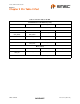
2-Port USB 2.0 Hub Controller Datasheet Chapter 2 Pin Table 2-Port Table 2.1 2-Port Pin Table for 36-QFN UPSTREAM USB 2.0 INTERFACE (3 PINS) USBDP0 USBDN0 VBUS_DET 2-PORT USB 2.
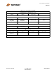
2-Port USB 2.0 Hub Controller Datasheet Table 2.2 2-Port Pin Table for 48-TQFP UPSTREAM USB 2.0 INTERFACE (3 PINS) USBDP0 USBDN0 VBUS_DET 2-PORT USB 2.0 INTERFACE (10 PINS) USBDP1 USBDN1 USBDP2 USBDN2 GR1/ NON_REM0 GR2/ NON_REM1 PRTPWR_POL RBIAS PRTPWR OCS_N SERIAL PORT INTERFACE (3 PINS) SDA/SMBDATA SCL/SMBCLK CFG_SEL0 CFG_SEL1 MISC (7 PINS) XTAL1/CLKIN XTAL2 RESET_N ATEST/ REG_EN CLKIN_EN TEST SELF_PWR POWER, GROUND AND NO CONNECT (25 PINS) Revision 2.
2-Port USB 2.
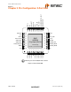
2-Port USB 2.0 Hub Controller 9'' &5 1& 6'$ 60%'$7$ 6&/ 60%&/. &)*B6(/ &)*B6(/ &/.,1B(1 7(67 5(6(7 9%86B'(7 966 966 9'' 1& Datasheet 9'' &5 1& 1& 966 1& 966 9'' ;7$/ 966 86% 74)3 ;7$/ &/.,1 9''$ 3// 1& 6(/)B3:5 9''$ 3// 2&6B1 9''$ 3// 3573:5 3573:5B32/ $7(67 5(*B(1 *5 121B5(0 5%,$6 *5 121B5(0 86%'1 86%'3 9''$ 9''$ 86%'3 86%'1 966 966 86%'1 86%'3 9''$ 966 966 Figure 3.
2-Port USB 2.0 Hub Controller Datasheet Chapter 4 2-Port Hub Block Diagram Upstream USB Data 8SVWUHDP VBUS 24 MHz Crystal To EEPROM or SMBus Master PLL Bus-Power 'HWHFW SD 1.8V 3.3V Upstream PHY 1.8V Reg Repeater SIE SCK Serial Interface Controller Port Controller Transaction Translator Routing Logic OC Sense Switch Driver LED Driver Strapping Options Downstream PHY #1 Downstream USB Data OC Sense Switch/LED Driver/optís Downstream PHY #2 Downstream USB Data Figure 4.
2-Port USB 2.0 Hub Controller Datasheet Table 4.1 2-Port Hub Pin Descriptions (continued) NAME SYMBOL TYPE FUNCTION 2-PORT USB 2.0 HUB INTERFACE High-Speed USB Data USBDN[2:1] USBDP[2:1] IO-U USB Power Enable PRTPWR O8 Port [2:1] Green LED & Port NonRemovable strapping option. GR[2:1]/ NON_REM[1:0] These pins connect to the downstream USB peripheral devices attached to the Hub’s ports. Enables power to USB peripheral devices (downstream).
2-Port USB 2.0 Hub Controller Datasheet Table 4.1 2-Port Hub Pin Descriptions (continued) NAME SYMBOL TYPE FUNCTION SERIAL PORT INTERFACE Serial Data/SMB Data SDA/SMBDATA IOSD12 (Serial Data)/(SMB Data) signal. Serial Clock/SMB Clock & Config Select 0 SCL/SMBCLK/ CFG_SEL0 IOSD12 (Serial Clock)/(SMB Clock) signal. This multifunction pin is read on the rising edge of RESET_N (see the applicable RESET_N timing table in Section 5.6.
2-Port USB 2.0 Hub Controller Datasheet Table 4.3 Miscellaneous Pins (continued) NAME SYMBOL TYPE FUNCTION Analog Test & Internal 1.8V voltage regulator enable ATEST/ REG_EN AIO This signal is used for testing the analog section of the chip, and to enable or disable the internal 1.8v regulator. This pin must be connected to VDDA33 to enable the internal 1.8V regulator, or to VSS to disable the internal regulator. When the internal regulator is enabled, the 1.
2-Port USB 2.0 Hub Controller Datasheet Table 4.5 Buffer Type Descriptions (continued) BUFFER DESCRIPTION IOSD12 Open drain….12mA sink with Schmitt trigger, and must meet I2C-Bus Specification Version 2.1 requirements. ICLKx XTAL Clock Input OCLKx XTAL Clock Output I-R RBIAS IO-U Defined in USB Specification. Note: Meets USB 1.1 requirements when operating as a 1.1-compliant device and meets USB 2.0 requirements when operating as a 2.0-compliant device. AIO Analog Input/output.
2-Port USB 2.0 Hub Controller Datasheet Chapter 5 Functional Block Description 5.1 2-Port Hub SMSC’s USB 2.0 2-Port Hub is fully specification compliant to the Universal Serial Bus Specification Revision 2.0 April 27,2000 (12/7/2000 and 5/28/2002 Errata). Please reference Chapter 11 (Hub Specification) for general details regarding Hub operation and functionality.
2-Port USB 2.0 Hub Controller Datasheet 5.1.1.5 High-Speed Disable Allows an OEM to force the Hub to configure as a Full-Speed device only (i.e. High-Speed not available). This field is set by the OEM using either the SMBus or EEPROM interface options. 5.1.1.6 EOP Disable During FS operation only, this permits the Hub to send EOP if no downstream traffic is detected at EOF1. See Section 11.3.1 of the USB 2.0 Specification for additional details.
2-Port USB 2.0 Hub Controller Datasheet When Dynamic Power switching is enabled, the Hub detects the availability of a local power source by monitoring the external SELF_PWR pin. If the Hub detects a change in power source availability, the Hub immediately disconnects and removes power from all downstream devices and disconnects the upstream port. The Hub will then re-attach to the upstream port as either a Bus-Powered Hub (if local-power in unavailable) or a Self-Powered Hub (if local power is available).
2-Port USB 2.0 Hub Controller Datasheet 5.2 EEPROM Interface The SMSC Hub can be configured via a 2-wire (I2C) EEPROM. (Please see Table 4.1, "7-Port Hub Pin Descriptions" for specific details on how to enable the I2C EEPROM option). The Internal state-machine will, (when configured for EEPROM support) read the external EEPROM for configuration data. The hub will then “attach” to the upstream USB host. Please see Table 5.1 User-Defined Descriptor Data for a list of data fields available. 5.2.
2-Port USB 2.0 Hub Controller Datasheet Table 5.1 User-Defined Descriptor Data (continued) DEFAULT CFG SELF (HEX) DEFAULT CFG BUS (HEX) 1 88 0C Configuration data byte #1 for Hub options. 7 1 90 90 Configuration data byte #2 for Hub options. Non Removable Device 8 1 00 00 Defines the ports that contain attached devices (this is used only when Hub is part of a compound device).
2-Port USB 2.0 Hub Controller Datasheet 5.2.3.3 EEPROM Offset 5:4(h) - Device ID BIT NUMBER BIT NAME 15:8 DID_MSB Most Significant Byte of the Device ID. 7:0 DID_LSB Least Significant Byte of the Device ID. 5.2.3.4 DESCRIPTION EEPROM Offset 6(h) - CONFIG_BYTE_1 BIT NUMBER BIT NAME 7 SELF_BUS_PWR DESCRIPTION Self or Bus Power: Selects between Self- and Bus-Powered operation. 0 = Bus-Powered operation. (BUS Default) 1 = Self-Powered operation.
2-Port USB 2.0 Hub Controller Datasheet BIT NUMBER BIT NAME DESCRIPTION 5:4 OC_TIMER OverCurrent Timer: Over Current Timer delay. 00 = 0.1ms 01 = 2ms (Default) 10 = 4ms 11 = 6ms 3 COMPOUND Compound Device: Designates if Hub is part of a compound device. 0 = No. (Default) 1 = Yes, Hub is part of a compound device. 2:0 5.2.3.6 Reserved Reserved.
2-Port USB 2.0 Hub Controller Datasheet 5.2.3.9 EEPROM Offset B(h) - Max Power For Self Powered Operation BIT NUMBER BIT NAME DESCRIPTION 7:0 MAX_PWR_SP Max Power Self_Powered: Value in 2mA increments that the Hub consumes from an upstream port (VBUS) when operating as a self-powered hub. This value includes the hub silicon along with the combined power consumption (from VBUS) of all associated circuitry on the board.
2-Port USB 2.0 Hub Controller Datasheet 5.2.3.12 EEPROM Offset E(h) - Hub Controller Max Current For Bus Powered Operation BIT NUMBER BIT NAME DESCRIPTION 7:0 HC_MAX_C_BP Hub Controller Max Current Bus-Powered: Value in 2mA increments that the Hub consumes from an upstream port (VBUS) when operating as a selfpowered hub. This value includes the hub silicon along with the combined power consumption (from VBUS) of all associated circuitry on the board.
2-Port USB 2.0 Hub Controller Datasheet 5.3.1.1 Byte Protocols When using the Hub SMBus Interface for byte transfers, a write will always consist of the SMBus Interface Slave Address byte, followed by the Internal Address Register byte, then the data byte. The normal read protocol consists of a write to the HUB with the SMBus Interface Address byte, followed by the Internal Address Register byte.
2-Port USB 2.0 Hub Controller Datasheet 5.3.4 Slave Device Time-Out According to the SMBus Specification, V1.0 devices in a transfer can abort the transfer in progress and release the bus when any single clock low interval exceeds 25ms (TTIMEOUT, MIN). Devices that have detected this condition must reset their communication and be able to receive a new START condition no later than 35ms (TTIMEOUT, MAX).
2-Port USB 2.0 Hub Controller Datasheet Table 5.
2-Port USB 2.0 Hub Controller Datasheet 5.3.9.3 Register 02h: Vendor ID (MSB) (Reset = 0x00) BIT NUMBER BIT NAME 7:0 VID_MSB 5.3.9.4 BIT NAME 7:0 PID_LSB BIT NAME 7:0 PID_MSB BIT NAME 7:0 DID_LSB DESCRIPTION Most Significant Byte of the Product ID. DESCRIPTION Least Significant Byte of the Device ID. Register 06h: Device ID (MSB) (Reset = 0x00) BIT NUMBER BIT NAME 7:0 DID_MSB 5.3.9.8 Least Significant Byte of the Product ID.
2-Port USB 2.0 Hub Controller Datasheet BIT NUMBER BIT NAME DESCRIPTION 5 HS_DISABLE High Speed Disable: Disables the capability to attach as either a High/Fullspeed device, and forces attachment as Full-speed only i.e. (no High-Speed support). 0 = High-/Full-Speed. 1 = Full-Speed-Only (High-Speed disabled!) 4 Reserved 3 EOP_DISABLE Reserved EOP Disable: Disables EOP generation of EOF1 when in Full-Speed mode. 0 = EOP generation is normal. 1 = EOP generation is disabled.
2-Port USB 2.0 Hub Controller Datasheet 5.3.9.10 Register 09h: Non-Removable Device (Reset = 0x00) BIT NUMBER BIT NAME DESCRIPTION 7:0 NR_DEVICE Non-Removable Device: Indicates which port(s) include non-removable devices. ‘0’ = port is removable, ‘1’ = port is non-removable. Bit 7:3: Reserved, always = ‘0’ Bit 2= 1; Port 2 non-removable. Bit 1= 1; Port 1 non removable. Bit 0 is Reserved, always = ‘0’. 5.3.9.
2-Port USB 2.0 Hub Controller Datasheet 5.3.9.14 Register 0Dh: Max Power For Bus Powered Operation (Reset = 0x00) BIT NUMBER BIT NAME DESCRIPTION 7:0 MAX_PWR_BP Max Power Bus_Powered: Value in 2mA increments that the Hub consumes from an upstream port (VBUS) when operating as a bus-powered hub. This value includes the hub silicon along with the combined power consumption (from VBUS) of all associated circuitry on the board.
2-Port USB 2.0 Hub Controller Datasheet 5.3.9.19 Reserved Registers Unless otherwise instructed, only a ‘0’ may be written to all reserved registers or bits. 5.4 Default Configuration Option: The SMSC Hub can be configured via its internal default configuration. (please see for specific details on how to enable default configuration. Please refer to Table 5.1 on page 19 for the internal default values that are loaded when this option is selected. 5.
2-Port USB 2.0 Hub Controller Datasheet 5.6.1 External Hardware RESET_N A valid hardware reset is defined as, assertion of RESET_N for a minimum of 1us after all power supplies are within operating range. While reset is asserted, the Hub (and its associated external circuitry) consumes less than 500μA of current from the upstream USB power source (300μA for the Hub and 200μA for the external circuitry). Assertion of RESET_N (external pin) causes the following: 1.
2-Port USB 2.0 Hub Controller Datasheet Table 5.5 Reset_N Timing for Default/Strap Option Mode (continued) NAME DESCRIPTION MIN t6 Host acknowledges attach and signals USB Reset. t7 USB Idle. t8 Completion time for requests (with or without data stage). TYP MAX UNITS 100 msec undefined msec 5 msec Notes: 5.6.1.2 When in Bus-Powered mode, the Hub and its associated circuitry must not consume more than 100mA from the upstream USB power source during t1+t5.
2-Port USB 2.0 Hub Controller Datasheet All Power Supplies must have reached the operating levels mandated in Section Chapter 7, "DC Parameters", prior to (or coincident with) the assertion of RESET_N. RESET_N for SMBus Slave Configuration 5.6.1.3 Hardware reset asserted Reset Negation t1 SMBus Code Load t2 Hub PHY Stabilization Attach USB Upstream t3 t4 USB Reset recovery Start completion request response Idle t6 t5 t7 RESET_N VSS Figure 5.4 Reset_N Timing for SMBus Mode Table 5.
2-Port USB 2.0 Hub Controller Datasheet 5.6.2 USB Bus Reset In response to the upstream port signaling a reset to the Hub, the Hub does the following: Note: The Hub does not propagate the upstream USB reset to downstream devices. 1. Sets default address to 0. 2. Sets configuration to: Unconfigured. 3. Negates PRTPWR to all downstream ports. 4. Clears all TT buffers. 5. Moves device from suspended to active (if suspended). 6. Complies with Section 11.10 of the USB 2.
2-Port USB 2.0 Hub Controller Datasheet Chapter 6 XNOR Test XNOR continuity tests all signal pins on the Hub (every pin except for NC, XTAL1/CLKIN, XTAL2, ATEST/REG_EN, RBIAS, TEST, Power, and Ground). This functionality is enabled by driving TEST and CFG_SEL[1] high, driving SCLK low and transition RESET_N from low to high. The output from the XNOR chain is driven to GR2 . For each pin tested for continuity GR2 should toggle. SMSC USB2502 37 DATASHEET Revision 2.
2-Port USB 2.0 Hub Controller Datasheet Chapter 7 DC Parameters 7.1 Maximum Guaranteed Ratings PARAMETER SYMBOL MIN MAX UNITS Storage Temperature TA -55 150 °C 325 °C Lead Temperature 1.8V supply voltage VDDA18PLL VDD18 -0.3 2.5 V 3.3V supply voltage VDDA33 VDDA33PLL -0.3 4.0 V Voltage on any I/O pin -0.3 (3.3V supply voltage + 2) ≤ 6 V Voltage on XTAL1 -0.3 4.0 V Voltage on XTAL2 -0.3 VDD18 + 0.
2-Port USB 2.0 Hub Controller Datasheet 7.2 Recommended Operating Conditions PARAMETER SYMBOL MIN MAX UNITS Operating Temperature TA 0 70 °C 1.8V supply voltage VDDA18PLL VDD18 1.62 1.98 V 3.3V supply voltage VDDA33 VDDA33PLL 3.0 3.6 V -0.3 5.5 V COMMENTS VDD33CR Voltage on any I/O pin If any 3.3V supply voltage drops b e l o w 3 . 0 V, t h e n t h e M A X becomes: (3.3V supply voltage + 0.5) Voltage on XTAL1 -0.3 VDDA33 V Voltage on XTAL2 -0.3 VDD18 V Table 7.
2-Port USB 2.0 Hub Controller Datasheet Table 7.1 DC Electrical Characteristics (continued) PARAMETER SYMBOL MIN TYP MAX UNITS 0.8 V COMMENTS ICLK Input Buffer Low Input Level VILCK High Input Level VIHCK 2.0 IIL -10 +10 uA VHYSC 50 100 mV 0.4 V Input Leakage Hysteresis TTL Levels V VIN = 0 to VDD33CR O8 and I/O8 Type Buffer Low Output Level High Output Level Output Leakage VOL VOH 2.4 IOL -10 V IOL = 8 mA @ VDD33CR = 3.3V IOH = -4mA @ VDD33CR = 3.3V +10 uA 0.
2-Port USB 2.0 Hub Controller Datasheet Table 7.1 DC Electrical Characteristics (continued) PARAMETER SYMBOL MIN TYP MAX UNITS COMMENTS Supply Current Suspend ICSBY 320 425 uA Total from all supplies. Supply Current Reset IRST 160 300 uA Total from all supplies. Notes: 1. Output leakage is measured with the current pins in high impedance. 2. See USB 2.0 Specification for USB DC electrical characteristics. 3. RBIAS is a 3.3V tolerant analog pin.
2-Port USB 2.0 Hub Controller Datasheet Chapter 8 AC Specifications 8.1 Oscillator/Clock Crystal: Parallel Resonant, Fundamental Mode, 24 MHz ±100ppm. External Clock: 50% Duty cycle ± 10%, 24 MHz ± 100ppm, Jitter < 100ps rms. 8.1.1 SMBus Interface: The SMSC Hub conforms to all voltage, power, and timing characteristics and specifications as set forth in the SMBus 1.0 Specification for Slave-Only devices (except as noted in Section 5.3). 8.1.2 I2C EEPROM: Frequency is fixed at 59KHz ± 20%. 8.1.
REVISION HISTORY D DESCRIPTION DATE RELEASED BY - SEE SPEC FRONT PAGE FOR REVISION HISTORY - - D2 D1 3 REVISION TERMINAL #1 IDENTIFIER AREA (D/2 X E/2) e 3 TERMINAL #1 IDENTIFIER AREA (D1/2 X E1/2) E1 E E2 EXPOSED PAD 0.6(MAX) 36X L 0.6(MAX) CHAMFERED CORNERS ARE OPTIONAL 4X 4 36X 0.
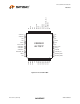
2-Port USB 2.0 Hub Controller Datasheet Figure 9.2 48 Pin TQFP Package Outline (7x7x1.4 mm body, 2mm Footprint) Table 9.1 48 Pin TQFP Package MIN NOMINAL MAX REMARKS A A1 A2 D D1 E E1 H L L1 ~ 0.05 1.35 8.80 6.90 8.80 6.90 0.09 0.45 ~ 1.60 0.15 1.45 9.20 7.10 9.20 7.10 0.20 0.75 ~ e θ ~ ~ ~ ~ ~ ~ ~ ~ 0.60 1.00 0.