USB2503/ USB2503A Integrated USB 2.0 Compatible 3-Port Hub PRODUCT FEATURES Datasheet Integrated USB 2.0 Compatible 3-Port Hub — 3 Transaction Translators for highest performance — High-Speed (480Mbits/s), Full-Speed (12Mbits/s) and Low-Speed (1.5Mbits/s) compatible — Full power management with per port or ganged, selectable power control — Detects Bus-Power/Self-Power source and changes mode automatically Complete USB Specification 2.
Integrated USB 2.0 Compatible 3-Port Hub Datasheet ORDER NUMBERS: USB2503/USB2503A-HZH FOR 48 PIN QFN LEAD-FREE ROHS COMPLIANT PACKAGE 80 ARKAY DRIVE, HAUPPAUGE, NY 11788 (631) 435-6000, FAX (631) 273-3123 Copyright © 2007 SMSC or its subsidiaries. All rights reserved. Circuit diagrams and other information relating to SMSC products are included as a means of illustrating typical applications. Consequently, complete information sufficient for construction purposes is not necessarily given.
Integrated USB 2.0 Compatible 3-Port Hub Datasheet Table of Contents Chapter 1 General Description . . . . . . . . . . . . . . . . . . . . . . . . . . . . . . . . . . . . . . . . . . . . . . . . . 6 1.1 OEM Selectable Features. . . . . . . . . . . . . . . . . . . . . . . . . . . . . . . . . . . . . . . . . . . . . . . . . . . . . . . . . 6 Chapter 2 Pin Table 3-Port . . . . . . . . . . . . . . . . . . . . . . . . . . . . . . . . . . . . . . . . . . . . . . . . . . . .
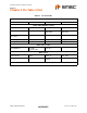
Integrated USB 2.0 Compatible 3-Port Hub Datasheet List of Figures Figure 3.1 Figure 4.1 Figure 5.1 Figure 5.2 Figure 5.3 Figure 5.4 Figure 9.1 3-Port 48-Pin QFN . . . . . . . . . . . . . . . . . . . . . . . . . . . . . . . . . . . . . . . . . . . . . . . . . . . . . . . . . . 8 3-Port Block Diagram . . . . . . . . . . . . . . . . . . . . . . . . . . . . . . . . . . . . . . . . . . . . . . . . . . . . . . . . 9 LED Strapping Option . . . . . . . . . . . . . . . . . . . . . . . . . . . . . . . . . . . . .
Integrated USB 2.0 Compatible 3-Port Hub Datasheet List of Tables Table 4.1 Table 4.2 Table 4.3 Table 4.4 Table 4.5 Table 5.1 Table 5.2 Table 5.3 Table 5.4 Table 5.5 Table 5.6 Table 5.7 Table 7.1 Table 9.1 3-Port Hub Pin Descriptions . . . . . . . . . . . . . . . . . . . . . . . . . . . . . . . . . . . . . . . . . . . . . . . . . . . 9 SMBus or EEPROM Interface Behavior . . . . . . . . . . . . . . . . . . . . . . . . . . . . . . . . . . . . . . . . . 11 Miscellaneous Pins . . . . . . . . . . . . . . . . .
Integrated USB 2.0 Compatible 3-Port Hub Datasheet Chapter 1 General Description The SMSC 3-Port Hub is fully compliant with the USB 2.0 Specification and will attach to a USB host as a Full-Speed Hub or as a Full-/High-Speed Hub. The 3-Port Hub supports Low-Speed, Full-Speed, and High-Speed (if operating as a High-Speed Hub) downstream devices on all of the enabled downstream ports. A dedicated Transaction Translator (TT) is available for each downstream facing port.
Integrated USB 2.0 Compatible 3-Port Hub Datasheet Chapter 2 Pin Table 3-Port Table 2.1 3-Port Pin Table UPSTREAM USB 2.
Integrated USB 2.
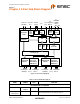
Integrated USB 2.0 Compatible 3-Port Hub Datasheet Chapter 4 3-Port Hub Block Diagram Upstream Upstream 24 MHz USB Data VBUS Crystal Upstream PHY VBUS Power Detect 3.3V To EEPROM Pin 1.8V Strapping or SMBus Master Cap Options SD SCL Internal Defaults Select 1.8V Reg. PLL Controller SIE Repeater TT #1 Serial Interface TT #2 TT #3 Port Controller Routing Logic Port #1 Downstream OC Sense PHY #1 Switch Driver LED Drivers ...
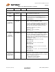
Integrated USB 2.0 Compatible 3-Port Hub Datasheet Table 4.1 3-Port Hub Pin Descriptions (continued) NAME SYMBOL TYPE FUNCTION 3-PORT USB 2.0 HUB INTERFACE High-Speed USB Data USBDN[3:1] USBDP[3:1] IO-U These pins connect to the downstream USB peripheral devices attached to the Hub’s ports. USB Power Enable PRTPWR[3:1] O12 Enables power to USB peripheral devices (downstream). Port 3 Green LED & Port Disable strapping option.
Integrated USB 2.0 Compatible 3-Port Hub Datasheet Table 4.1 3-Port Hub Pin Descriptions (continued) NAME SYMBOL TYPE Port Power Polarity strapping. PRTPWR_POL I/O12 FUNCTION Port Power Polarity strapping determination for the active signal polarity of the PRTPWR[3:1] pins.
Integrated USB 2.0 Compatible 3-Port Hub Datasheet Table 4.3 Miscellaneous Pins (continued) NAME SYMBOL TYPE FUNCTION Crystal Output XTAL2 OCLKx 24MHz Crystal This is the other terminal of the crystal, or left unconnected when an external clock source is used to drive XTAL1/CLKIN. It must not be used to drive any external circuitry other than the crystal circuit.
Integrated USB 2.0 Compatible 3-Port Hub Datasheet Table 4.4 Power, Ground, and No Connect (continued) NAME SYMBOL VDD3P3 CORE PLL VDD33CR VSS VSS TYPE FUNCTION +3.3V I/O and Core power. Ground. Table 4.5 Buffer Type Descriptions BUFFER I DESCRIPTION Input. IPD Input, with a weak Internal pull-down. IPU Input, with a weak Internal pull-up. IS Input with Schmitt trigger. O12 Output 12mA. I/O12 Input/Output, 12mA IOSD12 Open drain….
Integrated USB 2.0 Compatible 3-Port Hub Datasheet Chapter 5 Functional Block Description 5.1 3-Port Hub SMSC’s USB 2.0 3-Port Hub is fully specification compliant to the Universal Serial Bus Specification Revision 2.0 April 27,2000 (12/7/2000 and 5/28/2002 Errata). Please reference Chapter 11 (Hub Specification) for general details regarding Hub operation and functionality.
Integrated USB 2.0 Compatible 3-Port Hub Datasheet 5.1.1.5 Port Indicators Controls the use of LED indicator for Port status information. See Section 11.5.3 of the USB 2.0 Specification for additional details. This field is set by the OEM using either the SMBus or EEPROM interface options. 5.1.1.6 High-Speed Disable Allows an OEM to force the Hub to configure as a Full-Speed device only (i.e. High-Speed not available). This field is set by the OEM using either the SMBus or EEPROM interface options. 5.
Integrated USB 2.0 Compatible 3-Port Hub Datasheet This field is set by the OEM using either the SMBus or EEPROM interface options. When using the internal default option, the NON_REM[1:0] pins will designate the appropriate ports as being nonremovable. 5.1.1.13 Self-Powered Port DISABLE During Self-Powered operation, this selects the ports which will be permanently disabled, and are not available to be enabled or enumerated by a Host Controller.
Integrated USB 2.0 Compatible 3-Port Hub Datasheet 5.1.1.20 Bus-Powered Hub Controller Current When in Bus-Powered configuration, Maximum current requirements of the Hub Controller in 2mA increments. This field is set by the OEM using either the SMBus or EEPROM interface options. 5.1.1.21 Power-On Timer Time (in 2ms intervals) from the time power-on sequence begins on a port until power is good on that port.
Integrated USB 2.0 Compatible 3-Port Hub Datasheet 5.2.1.3 I2C EEPROM Slave Address Slave address is 1010000. Note: 10-bit addressing is NOT supported. 5.2.2 In-Circuit EEPROM Programming The EEPROM can be programmed via ATE by pulling RESET_N low (which tri-states the Hub’s EEPROM interface and allows an external source to program the EEPROM). 5.2.3 EEPROM DATA Table 5.1 User-Defined Descriptor Data DEFAULT CFG SELF (HEX) DEFAULT CFG BUS (HEX) 2 0424 0424 Vendor ID (assigned by USB-IF).
Integrated USB 2.0 Compatible 3-Port Hub Datasheet 5.2.3.1 EEPROM Offset 1:0(h) - Vendor ID BIT NUMBER BIT NAME 15:8 VID_MSB Most Significant Byte of the Vendor ID. 7:0 VID_LSB Least Significant Byte of the Vendor ID. 5.2.3.2 DESCRIPTION EEPROM Offset 3:2(h) - Product ID BIT NUMBER BIT NAME 15:8 PID_MSB Most Significant Byte of the Product ID. 7:0 PID_LSB Least Significant Byte of the Product ID. 5.2.3.
Integrated USB 2.0 Compatible 3-Port Hub Datasheet BIT NUMBER BIT NAME 3 EOP_DISABLE DESCRIPTION EOP Disable: Disables EOP generation at EOF1 when no downstream directed traffic is in progress. 0 = EOP generation at EOF1 is enabled. 1 = EOP generation at EOF1 is disabled, (normal operation). (Default) 2:1 CURRENT_SNS Over Current Sense: Indicates whether current sensing is on a port-by-port basis, or ganged. 00 = Ganged sensing (all ports together).
Integrated USB 2.0 Compatible 3-Port Hub Datasheet 5.2.3.6 EEPROM Offset 8(h) - Non-Removable Device BIT NUMBER BIT NAME DESCRIPTION 7:0 NR_DEVICE Non-Removable Device: Indicates which port(s) include non-removable devices. ‘0’ = port is removable, ‘1’ = port is non-removable. Bit 7= Reserved Bit 6= Reserved Bit 5= Reserved Bit 4= Reserved Bit 3= 1; Port 3 non-removable. Bit 2= 1; Port 2 non-removable. Bit 1= 1; Port 1 non removable. Bit 0 is Reserved, always = ‘0’. 5.2.3.
Integrated USB 2.0 Compatible 3-Port Hub Datasheet 5.2.3.9 EEPROM Offset B(h) - Max Power For Self Powered Operation BIT NUMBER BIT NAME DESCRIPTION 7:0 MAX_PWR_SP Max Power Self_Powered: Value in 2mA increments that the Hub consumes from an upstream port (VBUS) when operating as a self-powered hub. This value includes the hub silicon along with the combined power consumption (from VBUS) of all associated circuitry on the board.
Integrated USB 2.0 Compatible 3-Port Hub Datasheet 5.2.3.12 EEPROM Offset E(h) - Hub Controller Max Current For Bus Powered Operation BIT NUMBER BIT NAME DESCRIPTION 7:0 HC_MAX_C_BP Hub Controller Max Current Bus-Powered: Value in 2mA increments that the Hub consumes from an upstream port (VBUS) when operating as a selfpowered hub. This value includes the hub silicon along with the combined power consumption (from VBUS) of all associated circuitry on the board.
Integrated USB 2.0 Compatible 3-Port Hub Datasheet 5.3.1.1 Byte Protocols When using the Hub SMBus Interface for byte transfers, a write will always consist of the SMBus Interface Slave Address byte, followed by the Internal Address Register byte, then the data byte. The normal read protocol consists of a write to the HUB with the SMBus Interface Address byte, followed by the Internal Address Register byte.
Integrated USB 2.0 Compatible 3-Port Hub Datasheet 5.3.4 Slave Device Time-Out According to the SMBus Specification, V1.0 devices in a transfer can abort the transfer in progress and release the bus when any single clock low interval exceeds 25ms (TTIMEOUT, MIN). Devices that have detected this condition must reset their communication and be able to receive a new START condition no later than 35ms (TTIMEOUT, MAX).
Integrated USB 2.0 Compatible 3-Port Hub Datasheet Table 5.
Integrated USB 2.0 Compatible 3-Port Hub Datasheet 5.3.9.3 Register 02h: Vendor ID (MSB) (Reset = 0x00) BIT NUMBER BIT NAME 7:0 VID_MSB 5.3.9.4 BIT NAME 7:0 PID_LSB BIT NAME 7:0 PID_MSB BIT NAME 7:0 DID_LSB DESCRIPTION Most Significant Byte of the Product ID. DESCRIPTION Least Significant Byte of the Device ID. Register 06h: Device ID (MSB) (Reset = 0x00) BIT NUMBER BIT NAME 7:0 DID_MSB 5.3.9.8 Least Significant Byte of the Product ID.
Integrated USB 2.0 Compatible 3-Port Hub Datasheet BIT NUMBER BIT NAME DESCRIPTION 5 HS_DISABLE High Speed Disable: Disables the capability to attach as either a High/Fullspeed device, and forces attachment as Full-speed only i.e. (no High-Speed support). 0 = High-/Full-Speed. 1 = Full-Speed-Only (High-Speed disabled!) 4 MTT_ENABLE Multi-TT enable: Enables one transaction translator per port operation. 0 = single TT for all ports.
Integrated USB 2.0 Compatible 3-Port Hub Datasheet 5.3.9.10 Register 09h: Non-Removable Device (Reset = 0x00) BIT NUMBER BIT NAME DESCRIPTION 7:0 NR_DEVICE Non-Removable Device: Indicates which port(s) include non-removable devices. ‘0’ = port is removable, ‘1’ = port is non-removable. Bit Bit Bit Bit Bit Bit Bit Bit 5.3.9.11 7= Reserved 6= Reserved 5= Reserved 4= 1; Reserved . 3= 1; Port 3 non-removable. 2= 1; Port 2 non-removable. 1= 1; Port 1 non removable. 0 is Reserved, always = ‘0’.
Integrated USB 2.0 Compatible 3-Port Hub Datasheet 7:0 MAX_PWR_SP Max Power Self_Powered: Value in 2mA increments that the Hub consumes from an upstream port (VBUS) when operating as a self-powered hub. This value includes the hub silicon along with the combined power consumption (from VBUS) of all associated circuitry on the board.
Integrated USB 2.0 Compatible 3-Port Hub Datasheet 5.3.9.17 Register 10h: Power-On Time (Reset = 0x00) BIT NUMBER BIT NAME DESCRIPTION 7:0 POWER_ON_TIME Power On Time: The length of time that it takes (in 2 ms intervals) from the time the host initiated power-on sequence begins on a port until power is good on that port. 5.3.9.18 Undefined Registers The registers shown in Table 5.4 are the defined registers in the Hub. Reads to undefined registers return 00h.
Integrated USB 2.0 Compatible 3-Port Hub Datasheet +V Strap High 50K GR1 HUB GR2 Strap Low 50K Figure 5.1 LED Strapping Option 5.6 Reset There are two different resets that the Hub experiences. One is a hardware reset (via the RESET_N pin) and the second is a USB Bus Reset. 5.6.1 External Hardware RESET_N A valid hardware reset is defined as, assertion of RESET_N for a minimum of 1us after all power supplies are within operating range.
Integrated USB 2.0 Compatible 3-Port Hub Datasheet 5.6.1.1 RESET_N for Strapping Option Configuration Hardware reset asserted Drive Strap Outputs to inactive levels Read Strap Options t1 Attach USB Upstream USB Reset recovery t5 Start completion request response Idle t7 t6 t8 t2 t3 RESET_N VSS t4 Strap Pins Don’t Care Valid Driven by Hub if strap is an output. Don’t Care VSS Figure 5.2 Reset_N Timing for Default/Strap Option Mode Table 5.
Integrated USB 2.0 Compatible 3-Port Hub Datasheet 5.6.1.2 RESET_N for EEPROM Configuration Hardware reset asserted Attach USB Upstream Read EEPROM + Set Options Read Strap Options USB Reset recovery Start completion request response Idle t4 t1 t2 t5 t3 t6 t7 RESET_N VSS Figure 5.3 Reset_N Timing for EEPROM Mode Table 5.6 Reset_N Timing for EEPROM Mode NAME DESCRIPTION MIN t1 RESET_N Asserted. t2 Hub Recovery/Stabilization. t3 EEPROM Read / Hub Config. t4 USB Attach (See Note).
Integrated USB 2.0 Compatible 3-Port Hub Datasheet RESET_N for SMBus Slave Configuration 5.6.1.3 Hardware reset asserted Reset Negation SMBus Code Load t1 t2 Hub PHY Stabilization Attach USB Upstream t3 t4 USB Reset recovery Start completion request response Idle t6 t5 t7 RESET_N VSS Figure 5.4 Reset_N Timing for SMBus Mode Table 5.7 Reset_N Timing for SMBus Mode NAME DESCRIPTION MIN t1 RESET_N Asserted. t2 Hub Recovery/Stabilization. t3 SMBus Code Load (See Note).
Integrated USB 2.0 Compatible 3-Port Hub Datasheet 5. Moves device from suspended to active (if suspended). 6. Complies with Section 11.10 of the USB 2.0 Specification for behavior after completion of the reset sequence. The Host then configures the Hub and the Hub’s downstream port devices in accordance with the USB Specification. Revision 2.
Integrated USB 2.0 Compatible 3-Port Hub Datasheet Chapter 6 XNOR Test XNOR continuity tests all signal pins on the Hub (every pin except for NC, XTAL1/CLKIN, XTAL2, ATEST/REG_EN, RBIAS, TEST1, Power, and Ground). This functionality is enabled by driving TEST1 and CFG_SEL[1] high, driving SCLK low and transition RESET_N from low to high. The output from the XNOR chain is driven to GR2 . For each pin tested for continuity GR2 should toggle. SMSC USB2503/USB2503A 37 DATASHEET Revision 2.
Integrated USB 2.0 Compatible 3-Port Hub Datasheet Chapter 7 DC Parameters 7.1 Maximum Guaranteed Ratings PARAMETER SYMBOL MIN MAX UNITS Storage Temperature TA -55 150 °C 325 °C Lead Temperature 1.8V supply voltage VDDA18PLL VDD18 -0.5 2.5 V 3.3V supply voltage VDDA33 VDDA33PLL -0.5 4.0 V Voltage on any I/O pin -0.5 (3.3V supply voltage + 2) ≤ 6 V Voltage on XTAL1 -0.5 4.0 V Voltage on XTAL2 -0.5 VDD18 + 0.
Integrated USB 2.0 Compatible 3-Port Hub Datasheet 7.2 Recommended Operating Conditions PARAMETER SYMBOL MIN MAX UNITS Operating Temperature TA 0 70 °C 1.8V supply voltage VDDA18PLL VDD18 1.71 1.98 V 3.3V supply voltage VDDA33 VDDA33PLL 3.0 3.6 V -0.3 5.5 V COMMENTS VDD33CR Voltage on any I/O pin If any 3.3V supply voltage drops b e l o w 3 . 0 V, t h e n t h e M A X becomes: (3.3V supply voltage + 0.5) Voltage on XTAL1 -0.3 VDDA33 V Voltage on XTAL2 -0.3 VDD18 V Table 7.
Integrated USB 2.0 Compatible 3-Port Hub Datasheet Table 7.1 DC Electrical Characteristics (continued) PARAMETER SYMBOL MIN TYP MAX UNITS 0.8 V COMMENTS ICLK Input Buffer Low Input Level VILCK High Input Level VIHCK 2.0 IIL -10 +10 uA VHYSC 50 100 mV 0.4 V Input Leakage Hysteresis TTL Levels V VIN = 0 to VDD33CR O12 and I/O12 Type Buffer Low Output Level High Output Level Output Leakage VOL VOH 2.4 V IOL = 12mA @ VDD33CR = 3.3V IOH = -4mA @ VDD33CR = 3.
Integrated USB 2.0 Compatible 3-Port Hub Datasheet Table 7.1 DC Electrical Characteristics (continued) PARAMETER SYMBOL MIN TYP MAX UNITS COMMENTS Total from all supplies Supply Current Configured (Full-Speed Host) mA mA mA 1 Port 2 Ports 3 Ports IFCC1 IFCC2 IFCC3 150 155 160 Supply Current Suspend ICSBY 265 uA Total from all supplies. Supply Current Reset IRST 150 uA Total from all supplies. Notes: 1. Output leakage is measured with the current pins in high impedance. 2. See USB 2.
Integrated USB 2.0 Compatible 3-Port Hub Datasheet Chapter 8 AC Specifications 8.1 Oscillator/Clock Crystal: Parallel Resonant, Fundamental Mode, 24 MHz ±100ppm. External Clock: 50% Duty cycle ± 10%, 24 MHz ± 100ppm, Jitter < 100ps rms. 8.1.1 SMBus Interface: The SMSC Hub conforms to all voltage, power, and timing characteristics and specifications as set forth in the SMBus 1.0 Specification for Slave-Only devices (except as noted in Section 5.3). 8.1.2 I2C EEPROM: Frequency is fixed at 59KHz ± 20%.
Integrated USB 2.0 Compatible 3-Port Hub Datasheet Chapter 9 Package Outline Figure 9.1 48 Pin QFN Package Outline (7x7 mm body - 0.5 mm pitch) Table 9.1 48 Pin QFN Package Parameters A A1 A2 D D1 D2 E E1 E2 L e b ccc MIN NOMINAL MAX REMARKS 0.70 0 ~ 6.85 6.55 2.25 6.85 6.55 2.25 0.30 ~ 0.02 ~ 7.00 ~ ~ 7.00 ~ ~ ~ 0.50 Basic ~ ~ 1.00 0.05 0.80 7.15 6.95 5.60 7.15 6.95 5.60 0.