
- Standard Microsystems Compatible 3-Port Hub Specification Sheet

Integrated USB 2.0 Compatible 3-Port Hub
Datasheet
SMSC USB2503/USB2503A 31 Revision 2.3 (08-27-07)
DATASHEET
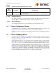
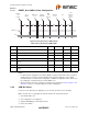
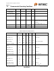
5.3.9.17 Register 10h: Power-On Time (Reset = 0x00)
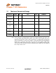
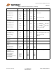
5.3.9.18 Undefined Registers
The registers shown in Table 5.4 are the defined registers in the Hub. Reads to undefined registers
return 00h. Writes to undefined registers have no effect and do not return an error.
5.3.9.19 Reserved Registers
Unless otherwise instructed, only a ‘0’ may be written to all reserved registers or bits.
5.4 Default Configuration Option:
The SMSC Hub can be configured via its internal default configuration. (please see Chapter 3, Pin
Configuration 3-Port Hub for specific details on how to enable default configuration.
Please refer to Table 5.1 on page 18 for the internal default values that are loaded when this option is
selected.
5.5 Default Strapping Options:
The SMSC Hub can be configured via a combination of internal default values and pin strap options.
Please see Table 4.1, "3-Port Hub Pin Descriptions" for specific details on how to enable the
default/pin-strap configuration option.
The strapping option pins only cover a limited sub-set of the configuration options. The internal default
values will be used for the bits & registers that are not controlled by a strapping option pin. Please
refer to Table 5.1 on page 18 for the internal default values that are loaded when this option is selected.
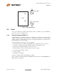
The Green LED pins are sampled after RESET_N negation, and the logic values are used to configure
the hub if the internal default configuration mode is selected. The implementation shown below (see
Figure 5.1) shows a recommended passive scheme. When a pin is configured with a “Strap High”
configuration, the LED functions with active low signalling, and the PAD will “sink” the current from the
external supply. When a pin is configured with a “Strap Low” configuration, the LED functions with
active high signalling, and the PAD will “source” the current to the external LED.
BIT
NUMBER BIT NAME DESCRIPTION
7:0 POWER_ON_TIME Power On Time: The length of time that it takes (in 2 ms intervals) from the
time the host initiated power-on sequence begins on a port until power is
good on that port.