
- Standard Microsystems Compatible 3-Port Hub Specification Sheet

Integrated USB 2.0 Compatible 3-Port Hub
Datasheet
Revision 2.3 (08-27-07) 43 SMSC USB2503/USB2503A
DATASHEET
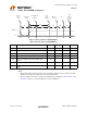
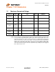
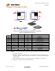
Chapter 9 Package Outline
Figure 9.1 48 Pin QFN Package Outline (7x7 mm body - 0.5 mm pitch)
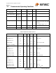
Notes:
1. Controlling Unit: millimeter.
2. Dimension b applies to plated terminals and is measured between 0.15mm and 0.30mm from the
terminal tip. Tolerance on the true position of the terminal is ± 0.05 mm at maximum material
conditions (MMC).
3. Details of terminal #1 identifier are optional but must be located within the zone indicated.
4. Coplanarity zone applies to exposed pad and terminals.
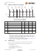
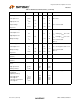
Table 9.1 48 Pin QFN Package Parameters
MIN NOMINAL MAX REMARKS
A 0.70 ~ 1.00 Overall Package Height
A1 0 0.02 0.05 Standoff
A2 ~ ~ 0.80 Mold Thickness
D 6.85 7.00 7.15 X Overall Size
D1 6.55 ~ 6.95 X Mold Cap Size
D2 2.25 ~ 5.60 X exposed Pad Size
E 6.85 7.00 7.15 Y Overall Size
E1 6.55 ~ 6.95 Y Mold Cap Size
E2 2.25 ~ 5.60 Y exposed Pad Size
L 0.30 ~ 0.50 Terminal Length
e 0.50 Basic Terminal Pitch
b 0.18 ~ 0.30 Terminal Width
ccc ~ ~ 0.08 Coplanarity