USB2524 USB MultiSwitchTM Hub PRODUCT FEATURES Datasheet USB 2.0 Compatible 4-Port Hub with two upstream host port connections — Provides electronic reconfiguration and re-assignment of any of its 4 downstream ports to either of two upstream host ports (“on-the-fly”). — Allows multiple USB hosts to share peripherals and enables a user to dynamically assign host ownership.
USB MultiSwitchTM Hub Datasheet ORDER NUMBER(S): USB2524-ABZJ for 56-pin QFN Lead-Free RoHS Compliant Package 80 ARKAY DRIVE, HAUPPAUGE, NY 11788 (631) 435-6000, FAX (631) 273-3123 Copyright © 2007 SMSC or its subsidiaries. All rights reserved. Circuit diagrams and other information relating to SMSC products are included as a means of illustrating typical applications. Consequently, complete information sufficient for construction purposes is not necessarily given.
USB MultiSwitchTM Hub Datasheet Table of Contents Chapter 1 General Description . . . . . . . . . . . . . . . . . . . . . . . . . . . . . . . . . . . . . . . . . . . . . . . . . 8 1.1 OEM Selectable Features. . . . . . . . . . . . . . . . . . . . . . . . . . . . . . . . . . . . . . . . . . . . . . . . . . . . . . . . . 9 Chapter 2 Pin Layout . . . . . . . . . . . . . . . . . . . . . . . . . . . . . . . . . . . . . . . . . . . . . . . . . . . . . . . 10 Chapter 3 Pin Configuration . . . . . . . . . . . .
USB MultiSwitchTM Hub Datasheet 7.2 7.3 7.1.4.28 Register D2h: Port Assign Interface Configuration 0B (Reset = 0x00) . . . . . . . . . . . . . . 7.1.4.29 Register D3h: Port Assign Interface Configuration 0C (Reset = 0x00) . . . . . . . . . . . . . . 7.1.4.30 Register D4h: Port Assign Interface Configuration 0D (Reset = 0x00) . . . . . . . . . . . . . . 7.1.4.31 Register D5h: Port Assign Interface Configuration 1A (Reset = 0x00) . . . . . . . . . . . . . . 7.1.4.
USB MultiSwitchTM Hub Datasheet 7.4 7.5 Default Strapping Option . . . . . . . . . . . . . . . . . . . . . . . . . . . . . . . . . . . . . . . . . . . . . . . . . . . . . . . . 43 Default Configuration . . . . . . . . . . . . . . . . . . . . . . . . . . . . . . . . . . . . . . . . . . . . . . . . . . . . . . . . . . . 43 Chapter 8 LED Interface Description . . . . . . . . . . . . . . . . . . . . . . . . . . . . . . . . . . . . . . . . . . 44 8.1 8.2 8.3 USB Mode: . . . . . . . . . . . . . . . . . . . .
USB MultiSwitchTM Hub Datasheet List of Figures Figure 3.1 Figure 5.1 Figure 7.1 Figure 7.2 Figure 7.3 Figure 8.1 Figure 9.1 Figure 9.2 Figure 9.3 Figure 13.1 USB2524 QFN-56 . . . . . . . . . . . . . . . . . . . . . . . . . . . . . . . . . . . . . . . . . . . . . . . . . . . . . . . . . USB2524 Switching Hub Block Diagram . . . . . . . . . . . . . . . . . . . . . . . . . . . . . . . . . . . . . . . . SMBus Block Write . . . . . . . . . . . . . . . . . . . . . . . . . . . . . . . . . . . . . . . . . . . .
USB MultiSwitchTM Hub Datasheet List of Tables Table 2.1 USB2524 56-Pin QFN Pin Configuration Table. . . . . . . . . . . . . . . . . . . . . . . . . . . . . . . . . . . . Table 4.1 Switching Hub Pin Descriptions. . . . . . . . . . . . . . . . . . . . . . . . . . . . . . . . . . . . . . . . . . . . . . . . Table 4.2 SMBus or EEPROM Interface Behavior . . . . . . . . . . . . . . . . . . . . . . . . . . . . . . . . . . . . . . . . . Table 4.3 Miscellaneous Pins . . . . . . . . . . . . . . . . . . . . . . . .
USB MultiSwitchTM Hub Datasheet Chapter 1 General Description The SMSC 4-Port USB 2.0 Switching Hub Controller acts as two independently controllable USB 2.0 Hubs in a single package with the ability to electronically reassign and reconfigure any of its 4 downstream ports to either of its two upstream USB ports. This allows two USB hosts to share peripherals and to dynamically reconfigure them. Any configuration of the downstream ports is possible except simultaneous connection to both upstream ports.
USB MultiSwitchTM Hub Datasheet 1.1 OEM Selectable Features A default configuration is available in the USB2524 following a reset. This configuration may be sufficient for some applications. Strapping option pins make it possible to modify a limited sub-set of the configuration options. The USB2524 may also be configured by an external EEPROM or a microcontroller. When using the microcontroller interface, the Hub appears as an SMBus slave device.
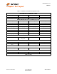
USB MultiSwitchTM Hub Datasheet Chapter 2 Pin Layout Table 2.1 USB2524 56-Pin QFN Pin Configuration Table UPSTREAM USB 2.0 INTERFACES (6 PINS) USBUP_DP1 USBUP_DM1 VBUS_DET1 VBUS_DET2 USBUP_DP2 USBUP_DM2 DOWNSTREAM 4-PORT USB 2.
USB MultiSwitchTM Hub Datasheet LED_B4_N CFG_SEL2 CFG_SEL1 SCL/SMBCLK/CFG_SEL0 SDA/SMBDATA 36 35 34 33 32 LED_B2_N SELF_PWR 37 29 VDD33 38 LED_B1_N PRT_ASSIGN3 39 LED_A1_N/NON_REM0 PRT_ASSIGN2 40 30 PRT_ASSIGN1 41 31 LED_A4_N/PRT_DIS1 PRT_ASSIGN0 42 Chapter 3 Pin Configuration 43 28 LED_A2_N/NON_REM1 RESET_N 44 27 PRTPWR1 VBUS_DET1 45 26 OCS1_N VBUS_DET2 46 25 OCS2_N VDDA33 47 24 PRTPWR2 USBUP_DP2 48 USBUP_DM2 49 VDDCR18 50 SMSC USB2524 XTAL2 51 (To
USB MultiSwitchTM Hub Datasheet Chapter 4 Switching Hub Pin Descriptions Table 4.1 Switching Hub Pin Descriptions NAME SYMBOL TYPE FUNCTION UPSTREAM USB 2.0 INTERFACE USB Bus Data USBUP_DP[2:1] USBUP_DM[2:1] IO-U Detect Upstream VBUS Power VBUS_DET[2:1] I/O These pins connect to the upstream USB bus data signals. Detects state of Upstream VBUS power. The SMSC Hub monitors VBUS_DET to determine when to assert the internal D+ pull-up resistor (signalling a connect event).
USB MultiSwitchTM Hub Datasheet Table 4.1 Switching Hub Pin Descriptions (continued) NAME SYMBOL TYPE Port [2:1] Green LED & Port NonRemovable strapping option LED_A[2:1]_N/ NON_REM[1:0] I/O12 FUNCTION Green indicator LED for ports 2 and 1. Will be active low when LED support is enabled via EEPROM or SMBus. If the hub is configured by the internal default configuration, these pins will be sampled at RESET_N negation to determine if ports [3:1] contain permanently attached (nonremovable) devices.
USB MultiSwitchTM Hub Datasheet Table 4.1 Switching Hub Pin Descriptions (continued) NAME SYMBOL TYPE FUNCTION Assign Downstream Ports to Upstream Host Ports PRT_ASSIGN [3:0] I Port Assign Interface: Operates in either Embedded mode, or Peripheral mode. See Chapter 6, Assigning Ports for additional details. SERIAL PORT INTERFACE Serial Data/SMB Data SDA/SMBDATA IOSD12 (Serial Data)/(SMB Data) signal. Serial Clock/SMB Clock & SCL/SMBCLK/ CFG_SEL0 IOSD12 (Serial Clock)/(SMB Clock) signal.
USB MultiSwitchTM Hub Datasheet Table 4.2 SMBus or EEPROM Interface Behavior (continued) NAME NAME NAME FUNCTION 1 0 0 Internal Default Configuration PRT_ASSIGN[3:0] = Peripheral Mode (Edge Triggered) LED Mode = Host Ownership Mode Strap options on pins LED_A[4:1]_N are enabled.
USB MultiSwitchTM Hub Datasheet Table 4.4 Power, Ground, and No Connect (continued) NAME SYMBOL VDD PLL VDDPLL18 TYPE FUNCTION +1.8V Filtered analog power for internal PLL. This pin must have a 4.7μF (or greater) ±20% (ESR <0.1Ω) capacitor to VSS VDD Analog I/O VDDA33 +3.3V Filtered analog PHY power, shared between adjacent ports. VSS VSS Ground NC NC No Connect Table 4.5 Buffer Type Descriptions BUFFER I DESCRIPTION Input. IPD Input, Weak Internal pull-down.
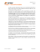
3 .3 V U p s tre a m V BUS 1 .8 V Reg.
USB MultiSwitchTM Hub Datasheet Chapter 6 Assigning Ports There are two different (OEM selectable) methods of assigning downstream ports to upstream hosts. One method is with the PRT_ASSIGN[3:0] interface through the use of mechanical switches or by electrical control of the pins via an external Microcontroller’s GPIO interface.
USB MultiSwitchTM Hub Datasheet Note 6.4 6.1.2 X = Don’t Care Peripheral Mode: Level Triggered In Peripheral Mode (Level Triggered), each pin directly switches a downstream port between the two upstream host ports. Each pin on the PRT_ASSIGN interface is only capable of two electrical states (either logic low or logic high). The interface will control downstream port assignment as follows. Note: There is a switching delay determined by the Register D0h: Port Interface Delay Timer.
USB MultiSwitchTM Hub Datasheet Chapter 7 Configuration Options 7.1 Switching Hub Configuration Options The SMSC Hub supports a large number of features (some are mutually exclusive), and must be configured in order to correctly function when attached to a USB host controller. There are three principal ways to configure the hub: SMBus, EEPROM, or by internal default settings (with or without pin strapping option over-rides).
USB MultiSwitchTM Hub Datasheet Table 7.
USB MultiSwitchTM Hub Datasheet 7.1.4.1 BIT NUMBER 7:0 7.1.4.2 BIT NUMBER 7:0 7.1.4.3 BIT NUMBER 7:0 7.1.4.4 BIT NUMBER 7:0 7.1.4.5 BIT NUMBER 7:0 7.1.4.6 BIT NUMBER 7:0 Register 00h: Vendor ID (LSB) (Reset = 0x00) BIT NAME VID_LSB DESCRIPTION Least Significant Byte of the Vendor ID. This is a 16-bit value that uniquely identifies the Vendor of the user device (assigned by USB-Interface Forum). This field is set by the OEM using either the SMBus or EEPROM interface options.
USB MultiSwitchTM Hub Datasheet 7.1.4.7 Register 06h: CONFIG_BYTE_1 (Reset = 0x00) BIT NUMBER 7 BIT NAME SELF_BUS_PWR DESCRIPTION Self or Bus Power: Selects between Self- and Bus-Powered operation. The Hub is either Self-Powered (draws less than 2mA of upstream bus power) or Bus-Powered (limited to a 100mA maximum of upstream power prior to being configured by the host controller). When configured as a Bus-Powered device, the SMSC Hub consumes less than 100mA of current prior to being configured.
USB MultiSwitchTM Hub Datasheet 7.1.4.8 BIT NUMBER 7 6 5:4 3 2:1 0 Register 07h: Configuration Data Byte 2 (Reset = 0x00) BIT NAME DYNAMIC Reserved OC_TIMER COMPOUND Reserved BOOST_IOUT DESCRIPTION Dynamic Power Enable: Controls the ability of the Hub to automatically change from Self-Powered operation to Bus- Powered operation if the local power source is removed or is unavailable (and from Bus-Powered to SelfPowered if the local power source is restored).
USB MultiSwitchTM Hub Datasheet BIT NUMBER 5 BIT NAME DESCRIPTION PRT_ASSIGN_CFG Port Assignment Configuration: 4:3 2:1 Reserved LED_MODE ‘0’ = Port assignment is controlled by hardware interface pins ‘1’ = Port assignment is controlled by: PORT_ASSIGN_12 PORT_ASSIGN_34 PORT_ASSIGN_56 PORT_ASSIGN_7 Reserved, always = ‘0’. LED Mode Selection: The LED_A[4:1]_N and LED_B[4:1]_N pins support several different modes of operation (depending upon OEM implementation of the LED circuit).
USB MultiSwitchTM Hub Datasheet 7.1.4.11 BIT NUMBER 7:0 Register 0Ah: Port Disable For Self Powered Operation (Reset = 0x00) BIT NAME PORT_DIS_SP DESCRIPTION Port Disable Self-Powered: Disables 1 or more contiguous ports. ‘0’ = port is available, ‘1’ = port is disabled. During Self-Powered operation, this selects the ports which will be permanently disabled, and are not available to be enabled or enumerated by a Host Controller.
USB MultiSwitchTM Hub Datasheet 7.1.4.14 Register 0Dh: Max Power For Bus Powered Operation (Reset = 0x00) BIT NUMBER 7:0 7.1.4.15 BIT NAME MAX_PWR_BP DESCRIPTION Max Power Bus_Powered: Value in 2mA increments that the Hub consumes from an upstream port (VBUS) when operating as a bus-powered hub. This value includes the hub silicon along with the combined power consumption (from VBUS) of all associated circuitry on the board.
USB MultiSwitchTM Hub Datasheet 7.1.4.20 BIT NUMBER 7:0 Register 13h: Manufacturer String Length (Reset = 0x00) BIT NAME MFR_STR_LEN DESCRIPTION Manufacturer String Length Maximum string length is 31 characters. 7.1.4.21 BIT NUMBER 7:0 Register 14h: Product String Length (Reset = 0x00) BIT NAME PRD_STR_LEN DESCRIPTION Product String Length Maximum string length is 31 characters 7.1.4.
USB MultiSwitchTM Hub Datasheet 7.1.4.25 Register 92h-CFh: Serial String (Reset = 0x00) BIT NUMBER 7:0 BIT NAME SER_STR DESCRIPTION Serial String, UNICODE UTF-16LE per USB 2.0 Specification Maximum string length is 31 characters (62 Bytes) Note: 7.1.4.
USB MultiSwitchTM Hub Datasheet 7.1.4.28 BIT NUMBER 7:0 7.1.4.29 BIT NUMBER 7:0 7.1.4.30 BIT NUMBER 7:0 7.1.4.31 BIT NUMBER 7:0 Register D2h: Port Assign Interface Configuration 0B (Reset = 0x00) BIT NAME PORT_INT_0B DESCRIPTION Port Assign Interface 0B: Determines the configuration of the hardware interface configuration for the assignment of ports 3 & 4 to upstream hosts.
USB MultiSwitchTM Hub Datasheet 7.1.4.32 Register D6h: Port Assign Interface Configuration 1B (Reset = 0x00) BIT NUMBER 7:0 7.1.4.33 BIT NAME PORT_INT_1B Register D7h: Port Assign Interface Configuration 1C (Reset = 0x00) BIT NUMBER 7:0 7.1.4.34 BIT NAME PORT_INT_1C DESCRIPTION Reserved, always = ‘0’. Register D8h: Port Assign Interface Configuration 1D (Reset = 0x00) BIT NUMBER 7:0 7.1.4.
USB MultiSwitchTM Hub Datasheet 7.1.4.36 BIT NUMBER 7:0 7.1.4.37 BIT NUMBER 7:0 7.1.4.38 BIT NUMBER 7:0 7.1.4.39 BIT NUMBER 7:0 Register DAh: Port Assign Interface Configuration 2B (Reset = 0x00) BIT NAME PORT_INT_2B DESCRIPTION Port Assign Interface 2B: Determines the configuration of the hardware interface configuration for the assignment of ports 3 & 4 to upstream hosts.
USB MultiSwitchTM Hub Datasheet 7.1.4.40 Register DEh: Port Assign Interface Configuration 3B (Reset = 0x00) BIT NUMBER 7:0 7.1.4.41 BIT NAME PORT_INT_3B Register DFh: Port Assign Interface Configuration 3C (Reset = 0x00) BIT NUMBER 7:0 7.1.4.42 BIT NAME PORT_INT_3C DESCRIPTION Reserved, always = ‘0’. Register E0h: Port Assign Interface Configuration 3D (Reset = 0x00) BIT NUMBER 7:0 7.1.4.
USB MultiSwitchTM Hub Datasheet 7.1.4.44 BIT NUMBER 7:0 7.1.4.45 BIT NUMBER 7:0 7.1.4.46 BIT NUMBER 7:0 7.1.4.47 BIT NUMBER 7:0 Register E2h: Port Assign Interface Configuration 4B (Reset = 0x00) BIT NAME PORT_INT_4B DESCRIPTION Port Assign Interface 4B: Determines the configuration of the hardware interface configuration for the assignment of ports 3 & 4 to upstream hosts.
USB MultiSwitchTM Hub Datasheet 7.1.4.48 Register E6h: Port Assign Interface Configuration 5B (Reset = 0x00) BIT NUMBER 7:0 7.1.4.49 BIT NAME PORT_INT_5B Register E7h: Port Assign Interface Configuration 5C (Reset = 0x00) BIT NUMBER 7:0 7.1.4.50 BIT NAME PORT_INT_5C DESCRIPTION Reserved, always = ‘0’. Register E8h: Port Assign Interface Configuration 5D (Reset = 0x00) BIT NUMBER 7:0 7.1.4.
USB MultiSwitchTM Hub Datasheet 7.1.4.52 BIT NUMBER 7:0 7.1.4.53 BIT NUMBER 7:0 7.1.4.54 BIT NUMBER 7:0 7.1.4.55 BIT NUMBER 7:0 Register EAh: Port Assign Interface Configuration 6B (Reset = 0x00) BIT NAME PORT_INT_6B DESCRIPTION Port Assign Interface 6B: Determines the configuration of the hardware interface configuration for the assignment of ports 3 & 4 to upstream hosts.
USB MultiSwitchTM Hub Datasheet 7.1.4.56 Register EEh: Port Assign Interface Configuration 7B (Reset = 0x00) BIT NUMBER 7:0 7.1.4.57 BIT NAME PORT_INT_7B Register EFh: Port Assign Interface Configuration 7C (Reset = 0x00) BIT NUMBER 7:0 7.1.4.58 BIT NAME PORT_INT_7C DESCRIPTION Reserved, always = ‘0’. Register F0h: Port Assign Interface Configuration 7D (Reset = 0x00) BIT NUMBER 7:0 7.1.4.
USB MultiSwitchTM Hub Datasheet 7.1.4.60 BIT NUMBER 7:0 7.1.4.61 BIT NUMBER 7:0 7.1.4.62 BIT NUMBER 7:0 7.1.4.63 BIT NUMBER 7:0 Register F2h: Port Assignment 3 & 4 (Reset = 0x00) BIT NAME DESCRIPTION PORT_ASSIGN_34 Port 3 & 4 Assignment to upstream host port.
USB MultiSwitchTM Hub Datasheet 7.1.4.64 Register FFh: Status/Command (Reset = 0x00) BIT NUMBER 7:3 2 BIT NAME Reserved INTF_PW_DN DESCRIPTION Reserved. {Note: Software must never write a ‘1’ to these bits} SMBus Interface Power Down 0 = Interface is active 1 = Interface power down after ACK has completed. 1 RESET {Note: This bit is write once and is only cleared by assertion of the external RESET_N pin.} Reset the SMBus Interface and internal memory back to RESET_N assertion default settings.
USB MultiSwitchTM Hub Datasheet 7.2 EEPROM Interface The SMSC Hub can be configured via a 2-wire (I2C) EEPROM (256x8). (please see Table 4.2, "SMBus or EEPROM Interface Behavior" for specific details on how to enable configuration via an I 2C EEPROM). The Internal state-machine will, (when configured for EEPROM support) read the external EEPROM for configuration data. The hub will then “attach” to the upstream USB port. Note: The Hub does not have the capability to write, or “Program”, an external EEPROM.
USB MultiSwitchTM Hub Datasheet 7.3 SMBus Slave Interface Instead of loading User-Defined Descriptor data from an external EEPROM, the SMSC Hub can be configured to receive a code load from an external processor via an SMBus interface. The SMBus interface shares the same pins as the EEPROM interface, if CFG_SEL2, CFG_SEL1 & CFG_SEL0 activates the SMBus interface, external EEPROM support is no longer available (and the user-defined descriptor data must be downloaded via the SMBus).
USB MultiSwitchTM Hub Datasheet A Block Read differs from a block write in that the repeated start condition exists to satisfy the I2C specification's requirement for a change in the transfer direction. Figure 7.2 SMBus Block Read 1 S 7 Slave Address 1 1 8 1 1 7 1 1 Wr A Register Address A S Slave Address Rd A ... 8 1 8 1 8 1 8 1 1 Byte Count = N A Data byte 1 A Data byte 2 A Data byte N A P Block Read 7.3.
USB MultiSwitchTM Hub Datasheet 7.3.7 Bus Reset Sequence The SMBus Slave Interface resets and returns to the idle state upon a START field followed immediately by a STOP field. 7.3.8 SMBus Alert Response Address The SMBALERT# signal is not supported by the Hub. 7.3.8.1 Undefined Registers Reads to undefined registers return 00h. Writes to undefined registers have no effect and do not return an error. 7.3.8.
USB MultiSwitchTM Hub Datasheet Chapter 8 LED Interface Description The USB2524 supports 3 different (mutually exclusive) LED modes. USB Mode provides 8 LEDS, which conform to the USB 2.0 specification functional requirements for Green and Amber LED’s. Basic Host Owner LED Indication mode uses 8 Single color LED’s to provide user indication of upstream host ownership of the 4 downstream ports.
USB MultiSwitchTM Hub Datasheet 8.3 Host Ownership and Port Speed LED Indication: All 8 LED pins are used in this mode in conjunction with 8 Dual-color LEDs (each LED pair in a single package) to indicate which upstream Host owns each specific downstream Port, as well as the speed that the downstream device is operating at. Each dual-color LED provides two separate colors (commonly Green and Red).
USB MultiSwitchTM Hub Datasheet The assignment is as follows: LED_A1_N = Port 1 Owned By Host A LED_B1_N = Port 1 Owned By Host B LED_A2_N = Port 2 Owned By Host A LED_B2_N = Port 2 Owned By Host B LED_A3_N = Port 3 Owned By Host A LED_B3_N = Port 3 Owned By Host B LED_A4_N = Port 4 Owned By Host A LED_B4_N = Port 4 Owned By Host B The Usage is as follows: LED_Ax_N Driven to Logic Low = Port Owned by Host “A” and is operating at USB LS/FS Speed LED_Ax_N Driven to Logic High = Port Owned by Host “A” and is
USB MultiSwitchTM Hub Datasheet Chapter 9 Reset 9.1 Reset There are two different resets that the Hub experiences. One is a hardware reset (via the RESET_N pin) and the second is a USB Bus Reset. 9.1.1 External Hardware RESET_N A valid hardware reset is defined as, assertion of RESET_N for a minimum of 1us after all power supplies are within operating range.
USB MultiSwitchTM Hub Datasheet 9.1.1.1 RESET_N for Strapping Option Configuration Hardware reset asserted Drive Strap Outputs to inactive levels Read Strap Options t1 Attach USB Upstream USB Reset recovery t5 Start completion request response Idle t7 t6 t8 t2 t3 RESET_N VSS t4 Strap Pins Don’t Care Valid Driven by Hub if strap is an output. Don’t Care VSS Figure 9.1 Reset_N Timing for Default/Strap Option Mode Table 9.
USB MultiSwitchTM Hub Datasheet 9.1.1.2 RESET_N for EEPROM Configuration Hardware reset asserted Read Strap Options Attach USB Upstream Read EEPROM + Set Options USB Reset recovery Start completion request response Idle t4 t1 t2 t5 t3 t6 t7 RESET_N VSS Figure 9.2 Reset_N Timing for EEPROM Mode Table 9.2 Reset_N Timing for EEPROM Mode NAME DESCRIPTION MIN t1 RESET_N Asserted. t2 Hub Recovery/Stabilization. t3 EEPROM Read / Hub Config. t4 USB Attach (See Note 9.
USB MultiSwitchTM Hub Datasheet 9.1.1.3 RESET_N for SMBus Slave Configuration Hardware reset asserted Reset Negation SMBus Code Load t1 t2 Hub PHY Stabilization Attach USB Upstream t3 t4 USB Reset recovery Start completion request response Idle t6 t5 t7 RESET_N VSS Figure 9.3 Reset_N Timing for SMBus Mode Table 9.3 Reset_N Timing for SMBus Mode NAME DESCRIPTION MIN t1 RESET_N Asserted. t2 Hub Recovery/Stabilization. t3 SMBus Code Load (See Note 9.
USB MultiSwitchTM Hub Datasheet Complies with Section 11.10 of the USB 2.0 Specification for behavior after completion of the reset sequence. The Host then configures the Hub and the Hub’s downstream port devices in accordance with the USB Specification. SMSC USB2524 51 DATASHEET Revision 1.
USB MultiSwitchTM Hub Datasheet Chapter 10 XNOR Test Please contact your SMSC representative for a detailed description of how this test mode is enabled and utilized. Revision 1.
USB MultiSwitchTM Hub Datasheet Chapter 11 DC Parameters 11.1 Maximum Guaranteed Ratings Operating Temperature Range . . . . . . . . . . . . . . . . . . . . . . . . . . . . . . . . . . . . . . . . . . . . . . 0oC to +70oC Storage Temperature Range. . . . . . . . . . . . . . . . . . . . . . . . . . . . . . . . . . . . . . . . . . . . . . . -55o to +150oC Lead Temperature Range (soldering, 10 seconds) . . . . . . . . . . . . . . . . . . . . . . . . . . . . . . . . . . .
USB MultiSwitchTM Hub Datasheet Table 11.1 DC Electrical Characteristics (continued) PARAMETER SYMBOL MIN TYP MAX UNITS 0.8 V COMMENTS Input Buffer with PullDown (IPD ) Low Input Level High Input Level Low Input Leakage VILI VIHI 2.0 TTL Levels V IILL 30 uA VIN = 0 IIHL 10 uA VIN = VDD33 Low Input Level VILCK 0.5 V TTL Levels High Input Level VIHCK 1.4 IIL -10 High Input Leakage ICLK Input Buffer Input Leakage V +10 uA VIN = 0 to VDD33 0.4 V IOL = 12 mA @ VDD33 = 3.
USB MultiSwitchTM Hub Datasheet Table 11.1 DC Electrical Characteristics (continued) PARAMETER SYMBOL MIN TYP MAX UNITS Supply Current Configured (2 upstream Full-Speed Hosts) 1 2 3 4 COMMENTS Total from all supplies Port Ports Ports Ports IFCC1 IFCC2 IFCC3 IFCC4 182 182 182 182 mA mA mA mA Supply Current Suspend ICSBY 272 μA Total from all supplies. Supply Current Reset ICRST 73 μA Total from all supplies. Note 11.1 Output leakage is measured with the current pins in high impedance.
USB MultiSwitchTM Hub Datasheet Chapter 12 AC Specifications 12.1 Oscillator/Clock Crystal: Parallel Resonant, Fundamental Mode, 24 MHz ±100ppm. External Clock: 50% Duty cycle ± 10%, 24 MHz ± 100ppm, Jitter < 100ps rms. 12.1.1 SMBus Interface: The SMSC Switching Hub conforms to all voltage, power, and timing characteristics and specifications as set forth in the SMBus 1.0 Specification for Slave-Only devices (except as noted in Section 7.3, "SMBus Slave Interface"). 12.1.
USB MultiSwitchTM Hub Datasheet Chapter 13 Package Outline Figure 13.1 USB2524 56-Pin QFN Package Outline and Parameters SMSC USB2524 57 DATASHEET Revision 1.