USB2640/USB2641 Ultra Fast USB 2.0 Multi-Format Flash Media Controller/USB Hub Combo Datasheet PRODUCT FEATURES General Description Features The SMSC USB2640/USB2641 is a USB 2.0 compliant, HiSpeed hub for USB port expansion with an attached mass storage class peripheral controller.
Ultra Fast USB 2.0 Multi-Format Flash Media Controller/USB Hub Combo ORDER NUMBER(S): USB2640/USB2641-HZH for 48-PIN, QFN LEAD-FREE RoHS COMPLIANT PACKAGE “XX” in the order number indicates the internal ROM firmware revision level. Please contact your SMSC representative for more information. 80 ARKAY DRIVE, HAUPPAUGE, NY 11788 (631) 435-6000, FAX (631) 273-3123 Copyright © 2008 SMSC or its subsidiaries. All rights reserved.
Ultra Fast USB 2.0 Multi-Format Flash Media Controller/USB Hub Combo Table of Contents Chapter 1 Overview . . . . . . . . . . . . . . . . . . . . . . . . . . . . . . . . . . . . . . . . . . . . . . . . . . . . . . . . . . 7 1.1 1.2 Device Features . . . . . . . . . . . . . . . . . . . . . . . . . . . . . . . . . . . . . . . . . . . . . . . . . . . . . . . . . . . . . . . . 8 OEM Selectable Features. . . . . . . . . . . . . . . . . . . . . . . . . . . . . . . . . . . . . . . . . . . . . . . . . . . . . . .
Ultra Fast USB 2.0 Multi-Format Flash Media Controller/USB Hub Combo Chapter 12 GPIO Usage . . . . . . . . . . . . . . . . . . . . . . . . . . . . . . . . . . . . . . . . . . . . . . . . . . . . . . 60 Revision 2.
Ultra Fast USB 2.0 Multi-Format Flash Media Controller/USB Hub Combo List of Tables Table 4.1 USB2640 48-Pin Table . . . . . . . . . . . . . . . . . . . . . . . . . . . . . . . . . . . . . . . . . . . . . . . . . . . . . . Table 4.2 USB2641 48-Pin Table . . . . . . . . . . . . . . . . . . . . . . . . . . . . . . . . . . . . . . . . . . . . . . . . . . . . . . Table 6.1 USB2640/USB2641 Pin Descriptions . . . . . . . . . . . . . . . . . . . . . . . . . . . . . . . . . . . . . . . . . . . Table 6.
Ultra Fast USB 2.0 Multi-Format Flash Media Controller/USB Hub Combo List of Figures Figure 3.1 Figure 3.2 Figure 5.1 Figure 5.2 Figure 6.1 Figure 6.2 Figure 6.3 Figure 6.4 Figure 6.5 Figure 7.1 Figure 8.1 Figure 9.1 Figure 10.1 Figure 10.2 Figure 11.1 USB2640 48-Pin QFN . . . . . . . . . . . . . . . . . . . . . . . . . . . . . . . . . . . . . . . . . . . . . . . . . . . . . . USB2641 48-Pin QFN . . . . . . . . . . . . . . . . . . . . . . . . . . . . . . . . . . . . . . . . . . . . . . . . . . . . . .
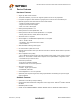
Ultra Fast USB 2.0 Multi-Format Flash Media Controller/USB Hub Combo Chapter 1 Overview The SMSC USB2640/USB2641 is an integrated USB 2.0 compliant, Hi-Speed hub for USB port expansion with an attached bulk only mass storage class peripheral controller. This multi-format flash media controller and USB Hub Combo features 3 downstream ports: one port is dedicated to an internally connected ultra fast flash media reader/writer and 2 exposed downstream ports are available for external peripheral expansion.
Ultra Fast USB 2.0 Multi-Format Flash Media Controller/USB Hub Combo 1.
Ultra Fast USB 2.0 Multi-Format Flash Media Controller/USB Hub Combo 1.2 OEM Selectable Features Hub A default configuration is available in the USB2640/USB2641 following a reset. The USB2640/USB2641 may also be configured by an external I2C EEPROM or via external SPI flash. The USB2640/USB2641 supports several OEM selectable features: Compound device support (port is permanently hardwired to a downstream USB peripheral device), on a port-by-port basis.
Ultra Fast USB 2.
Ultra Fast USB 2.
GPIO2 / RXD GPIO10 (CRD_PWR) VDD33 SD_D2 SD_D3 / MS_D3 GPIO12 / MS_INS SD_D4 / MS_D2 GPIO14 NC NC NC VDD33 36 35 34 33 32 31 30 29 28 27 26 25 Ultra Fast USB 2.
Ultra Fast USB 2.0 Multi-Format Flash Media Controller/USB Hub Combo Chapter 4 Pin Tables 4.1 48-Pin Tables Table 4.
Ultra Fast USB 2.0 Multi-Format Flash Media Controller/USB Hub Combo Table 4.
SMSC USB2640/USB2641 DATASHEET 15 USB Data Downstream PHY 3.3V Transaction Translator Serial Interface Engine 1.8V Reg PLL 24 MHz Crystal USB Data OC Sense/ Downstream Pwr Switch PHY Port #2 OC Sense Switch Driver Routing & Port Re-Ordering Logic OC Sense/ Pwr Switch Port #3 OC Sense Switch Driver Upstream PHY Bus-Power Detect/VBUS Pulse Repeater Upstream USB Data To Upstream VBUS 1.
Revision 2.0 (10-03-08) DATASHEET 16 USB Data Downstream PHY 3.3V Transaction Translator Serial Interface Engine 1.8V Reg PLL 24 MHz Crystal USB Data OC Sense/ Downstream Pwr Switch PHY Port #2 OC Sense Switch Driver Routing & Port Re-Ordering Logic OC Sense/ Pwr Switch Port #3 OC Sense Switch Driver Upstream PHY Bus-Power Detect/VBUS Pulse Repeater Upstream USB Data To Upstream VBUS 1.
Ultra Fast USB 2.0 Multi-Format Flash Media Controller/USB Hub Combo Chapter 6 Pin Descriptions This section provides a detailed description of each signal. The signals are arranged in functional groups according to their associated interface. The “n” symbol in the signal name indicates that the active, or asserted, state occurs when the signal is at a low voltage level. When “n” is not present before the signal name, the signal is asserted when at the high voltage level.
Ultra Fast USB 2.0 Multi-Format Flash Media Controller/USB Hub Combo Table 6.1 USB2640/USB2641 Pin Descriptions (continued) NAME SYMBOL 48-PIN QFN BUFFER TYPE xD Write Enable xD_nWE 22 O12PU DESCRIPTION This pin is an active low write strobe signal for the xD device. When using the internal FET, this pin has an internal weak pull-up resistor that is tied to the output of the internal Power FET, and is controlled by the xD_PU bit of the xDC_CTL register.
Ultra Fast USB 2.0 Multi-Format Flash Media Controller/USB Hub Combo Table 6.1 USB2640/USB2641 Pin Descriptions (continued) NAME SYMBOL MS System Data In/Out MS_D[7:0] 48-PIN QFN BUFFER TYPE 20 19 17 18 32 30 23 24 I/O12PD DESCRIPTION These pins are the bi-directional data signals for the MS device. In serial mode, the most significant bit (MSB) of each byte is transmitted first by either MSC or MS device on MS_D0. MS_D0, MS_D2, and MS_D3 have weak pulldown resistors.
Ultra Fast USB 2.0 Multi-Format Flash Media Controller/USB Hub Combo Table 6.1 USB2640/USB2641 Pin Descriptions (continued) NAME USB Power Enable SYMBOL PRTCTL[3:2] 48-PIN QFN BUFFER TYPE 7 6 I/OD12PU DESCRIPTION As an output, these pins enables power downstream USB peripheral devices. See Section 6.3, "Port Power Control" for diagram and usage instructions. As an input, when the power is enabled, these pins monitor the over-current condition.
Ultra Fast USB 2.0 Multi-Format Flash Media Controller/USB Hub Combo Table 6.1 USB2640/USB2641 Pin Descriptions (continued) NAME SYMBOL SPI Clock SPI_CLK / GPIO4 / SCL 48-PIN QFN BUFFER TYPE 9 I/O12 DESCRIPTION SPI_CLK: This is the SPI clock out to the serial ROM. See Section 6.4, "ROM BOOT Sequence" for diagram and usage instructions. When the SPI interface is disabled, by setting the SPI_DISABLE bit in the UTIL_CONFIG1 register, this pin becomes GPIO4. During reset, this pin must be driven low.
Ultra Fast USB 2.0 Multi-Format Flash Media Controller/USB Hub Combo Table 6.1 USB2640/USB2641 Pin Descriptions (continued) NAME SYMBOL 48-PIN QFN BUFFER TYPE DESCRIPTION MISC General Purpose I/O GPIO1 / LED1 / TXD 37 I/O12 GPIO: This pin may be used either as input, edge sensitive interrupt input, or output. LED: In addition, as an output, the GPIO1 can be used as output controlled by the LED1_GPIO1 register.
Ultra Fast USB 2.0 Multi-Format Flash Media Controller/USB Hub Combo 6.2 Buffer Type Descriptions Table 6.2 USB2640/USB2641 Buffer Type Descriptions BUFFER DESCRIPTION I Input. IPU Input, weak internal pull-up. IS Input with Schmitt trigger. I/O12 Input/output buffer with 12 mA sink and 12 mA source. I/O200 Input/output buffer 12 mA with FET disabled, 100/200 mA source only when the FET is enabled.
Ultra Fast USB 2.0 Multi-Format Flash Media Controller/USB Hub Combo 6.3 Port Power Control Port Power Control Using USB Power Switch The USB2640/USB2641 has a single port power control and over-current sense signal for each downstream port. When disabling port power, the driver will actively drive a '0'. To avoid unnecessary power dissipation, the internal pull-up resistor will be disabled at that time.
Ultra Fast USB 2.0 Multi-Format Flash Media Controller/USB Hub Combo Port Power Control Using a Poly Fuse When using the USB2640/USB2641 with a poly fuse, an external diode must be used (See Figure 6.2). When disabling port power, the driver will drive a '0'. This procedure will have no effect since the external diode will isolate the pin from the load. When port power is enabled, the output driver is disabled, and the pull-up resistor is enabled which creates an open drain output.
Ultra Fast USB 2.0 Multi-Format Flash Media Controller/USB Hub Combo 6.4 ROM BOOT Sequence After power-on reset, the internal firmware checks for an external SPI flash device that contains a valid signature of "2DFU" (device firmware upgrade) beginning at address 0xFFFA. If a valid signature is found, then the external ROM is enabled and code execution begins at address 0x0000 in the external SPI device. Otherwise, code execution continues from the internal ROM.
Ultra Fast USB 2.0 Multi-Format Flash Media Controller/USB Hub Combo Chapter 7 Configuration Options 7.1 Hub SMSC’s USB 2.0 hub is fully compliant to the Universal Serial Bus Specification available from the USB Implementer’s Forum found at http://www.usb.org (Revision 2.0 April 27, 2000 and the 12/7/2000 and 5/28/2002 Errata) . Please reference Chapter 11 (Hub Specification) for general details regarding hub operation and functionality.
Ultra Fast USB 2.0 Multi-Format Flash Media Controller/USB Hub Combo configuration, the OEM can update the values through the USB interface. The hub will then “attach” to the upstream USB host. When using an external SPI Flash, the register addresses in the following three tables (Table 7.1, Table 7.2, ) refer to offsets from the starting location ‘FE80h’. 7.3.2 EEPROM Data Descriptor Table 7.
Ultra Fast USB 2.0 Multi-Format Flash Media Controller/USB Hub Combo Table 7.1 Internal Flash Media Controller Configurations (continued) REG ADDR REGISTER NAME REGISTER DESCRIPTION DEFAULT VALUE CEh - D2h INQ_PRD_STR Inquiry Product String 2640 D3h DYN_NUM_LUN Dynamic Number of Luns FFh D4h - D7h LUN_DEV_MAP Lun to Device Mapping FFh, FFh, FFh, FFh D8h - DAh Reserved - 00h, 04h, 09h DBh - DDh Reserved - 5Ch, 59h, 9Ah Note 7.
Ultra Fast USB 2.0 Multi-Format Flash Media Controller/USB Hub Combo Table 7.3 Other Internal Configurations REG ADDR REGISTER NAME REGISTER DESCRIPTION DEFAULT VALUE F4h MS_SD_CLK_LIM MS/SD Clock Limit for Flash Media Controller 00h F5h N/A Reserved 66h F6h N/A Reserved 00h F7-FBh N/A Reserved 00h FCh-FFh NVSTORE_SIG Non-volatile storage signature (“ATA2”) “ATA2” 7.3.2.
Ultra Fast USB 2.0 Multi-Format Flash Media Controller/USB Hub Combo 7.3.2.5 22h-5Dh: USB Manufacturer String Length BYTE NUMBER BYTE NAME 59:0 USB_MFR_STR DESCRIPTION Manufacturer String Length Maximum string length is 28 characters. (See Note 7.2 below) 7.3.2.6 5Eh-99h: USB Product String Length BYTE NUMBER BYTE NAME 59:0 USB_PRD_STR DESCRIPTION Product String Length This string will be used during the USB enumeration process in Windows. Maximum string length is 28 characters. (See Note 7.
Ultra Fast USB 2.0 Multi-Format Flash Media Controller/USB Hub Combo 7.3.2.8 9Bh: USB MaxPower (1 byte) BYTE NUMBER BYTE NAME DESCRIPTION 7:0 USB_MAX_PWR USB Max Power Per USB specification. Do NOT set this value greater than 100 mA. 7.3.2.9 9Ch-9Fh: Attribute Byte Descriptions BYTE BYTE NAME BIT NUMBER 1 ATT_LB 3:0 4 DESCRIPTION Always reads ‘0’. Inquire Manufacturer and Product ID Strings 1 - Use the Inquiry Manufacturer and Product ID Strings.
Ultra Fast USB 2.0 Multi-Format Flash Media Controller/USB Hub Combo 7.3.2.10 A4h-A5h: LUN Power Configuration The USB2640/USB2641 has one internal FET which can be utilized for card power. The settings are stored in NVSTORE and provide the following features: 1.A card can be powered by an external FET or internal FET. 2.The power limit can be set to 100 mA (Default) or 200 mA for the internal FET. Each media uses two bytes to store its LUN power configuration. Bit 3 selects between internal or external.
Ultra Fast USB 2.0 Multi-Format Flash Media Controller/USB Hub Combo 7.3.3.1 AAh-B0h: Lun 0 Identifier String BYTE NUMBER BYTE NAME STRING DESCRIPTION 6:0 LUN0_ID_STR “COMBO” These bytes are used to specify the LUN descriptor returned by the device. These bytes are used in combination with the LUN to device mapping bytes in applications where the OEM wishes to reorder and rename the LUNs or utilizes a combo socket and wishes to rename the LUN. 7.3.3.
Ultra Fast USB 2.0 Multi-Format Flash Media Controller/USB Hub Combo 7.3.3.6 CEh-D2h: Inquiry Product String BYTE NUMBER BYTE NAME UINT DESCRIPTION 4:0 INQ_PRD_STR 2640 If bit 4 of the 1st attribute byte is set, the device will use these strings in response to a USB inquiry command, instead of the USB Descriptor Manufacturer and Product ID Strings. 7.3.3.
Ultra Fast USB 2.0 Multi-Format Flash Media Controller/USB Hub Combo 7.3.3.9 D8h-DAh: Reserved BIT NUMBER BYTE NAME BITS 2:0 Reserved 00h, 04h, 09h 7.3.3.10 For internal use only. DBh-DDh: Reserved BIT NUMBER BYTE NAME BITS 2:0 Reserved 5Ch, 59h, 9Ah 7.3.3.11 DESCRIPTION DESCRIPTION For internal use only. DEh: Vendor ID (LSB) BIT NUMBER BYTE NAME DESCRIPTION 7:0 VID_LSB Least Significant Byte of the Vendor ID.
Ultra Fast USB 2.0 Multi-Format Flash Media Controller/USB Hub Combo 7.3.3.14 E1h: Product ID (MSB) BIT NUMBER BIT NAME DESCRIPTION 7:0 PID_MSB Most Significant Byte of the Product ID. This is a 16-bit value that the Vendor can assign that uniquely identifies this particular product. 7.3.3.15 E2h: Device ID (LSB) BIT NUMBER BIT NAME 7:0 DID_LSB 7.3.3.16 Least Significant Byte of the Device ID. This is a 16-bit device release number in BCD (binary coded decimal) format.
Ultra Fast USB 2.0 Multi-Format Flash Media Controller/USB Hub Combo BIT NUMBER BIT NAME DESCRIPTION 5 HS_DISABLE Hi-Speed Disable: Disables the capability to attach as either a Hi-/Full-Speed device, and forces attachment as Full-Speed only (i.e. no Hi-Speed support). 0 = Hi-/Full-Speed 1 = Full-Speed-Only (Hi-Speed disabled!) 4 Reserved 3 EOP_DISABLE Always reads ‘0’. EOP Disable: Disables EOP generation of EOF1 when in Full-Speed mode.
Ultra Fast USB 2.0 Multi-Format Flash Media Controller/USB Hub Combo BIT NUMBER BIT NAME DESCRIPTION 3 COMPOUND Compound Device: Allows OEM to indicate that the hub is part of a compound (see the USB Specification for definition) device. The applicable port(s) must also be defined as having a "Non-Removable Device". Note: When configured via strapping options, declaring a port as nonremovable automatically causes the hub controller to report that it is part of a compound device.
Ultra Fast USB 2.0 Multi-Format Flash Media Controller/USB Hub Combo 7.3.3.20 E7h: Non-Removable Device BIT NUMBER BYTE NAME 7:0 NR_DEVICE DESCRIPTION Non-removable Device: Indicates which port(s) include non-removable devices. ‘0’ = port is removable, ‘1’ = port is non-removable. Informs the host if one of the active ports has a permanent device that is undetachable from the hub. (Note: The device must provide its own descriptor data.
Ultra Fast USB 2.0 Multi-Format Flash Media Controller/USB Hub Combo 7.3.3.22 E9h: Port Disable For Bus-Powered Operation BIT NUMBER BYTE NAME DESCRIPTION 7:0 PORT_DIS_BP Port Disable Bus-Powered: Disables 1 or more ports. ‘0’ = port is available, ‘1’ = port is disabled. During Self-Powered operation, this register selects the ports which will be permanently disabled. The ports are unavailable to be enabled or enumerated by a Host Controller.
Ultra Fast USB 2.0 Multi-Format Flash Media Controller/USB Hub Combo 7.3.3.25 ECh: Hub Controller Max Current For Self-Powered Operation BIT NUMBER BYTE NAME DESCRIPTION 7:0 HC_MAX_C_SP Hub Controller Max Current Self-Powered: Value in 2 mA increments that the hub consumes from an upstream port (VBUS) when operating as a selfpowered hub. This value includes the hub silicon along with the combined power consumption (from VBUS) of all associated circuitry on the board.
Ultra Fast USB 2.0 Multi-Format Flash Media Controller/USB Hub Combo 7.3.3.28 EFh: Boost_Up BIT NUMBER BIT NAME 7:2 Reserved 1:0 BOOST_IOUT DESCRIPTION Reserved USB electrical signaling drive strength Boost Bit for the Upstream Port ‘A’.
Ultra Fast USB 2.0 Multi-Format Flash Media Controller/USB Hub Combo 7.3.3.30 F1h: Port Swap BIT NUMBER BYTE NAME DESCRIPTION 7:0 PRT_SWP Port Swap: Swaps the Upstream and Downstream USB DP and DM Pins for ease of board routing to devices and connectors. ‘0’ = USB D+ functionality is associated with the DP pin and D- functionality is associated with the DM pin. ‘1’ = USB D+ functionality is associated with the DM pin and D- functionality is associated with the DP pin.
Ultra Fast USB 2.0 Multi-Format Flash Media Controller/USB Hub Combo 7.3.3.31 F2h: Port Remap 12 BIT NUMBER BYTE NAME 7:0 PRTR12 DESCRIPTION Port remap register for ports 1 & 2. When a hub is enumerated by a USB Host Controller, the hub is only permitted to report how many ports it has; the hub is not permitted to select a numerical range or assignment. The Host Controller will number the downstream ports of the hub starting with the number '1', up to the number of ports that the hub reported having.
Ultra Fast USB 2.0 Multi-Format Flash Media Controller/USB Hub Combo 7.3.3.32 F3h: Port Remap 3 BIT NUMBER BYTE NAME 7:0 PRTR3 DESCRIPTION Port remap register for port 3. When a hub is enumerated by a USB Host Controller, the hub is only permitted to report how many ports it has; the hub is not permitted to select a numerical range or assignment. The Host Controller will number the downstream ports of the hub starting with the number '1', up to the number of ports that the hub reported having.
Ultra Fast USB 2.0 Multi-Format Flash Media Controller/USB Hub Combo 7.3.3.33 F4h: MS/SD Clock Limit BYTE NAME MS_SD_CLK_LIM 7.3.3.34 TYPE BITS DESCRIPTION Upper Nibble Bits 7:4 0: 1: 2: 3: MS MS MS MS Lower Nibble Bits 3:0 0: 1: 2: 3: SD/MMC SD/MMC SD/MMC SD/MMC BYTE NAME DEFAULT VALUE 7:0 Reserved 66h MHz -- Default, no limit MHz MHz MHz - 48 24 20 15 MHz MHz MHz MHz DESCRIPTION Reserved. F6h: Reserved BIT NUMBER BYTE NAME DEFAULT VALUE 7:0 Reserved 00h 7.3.3.
Ultra Fast USB 2.0 Multi-Format Flash Media Controller/USB Hub Combo 7.3.4.1 Implementation Characteristics The device will only access an EEPROM using the Sequential Read Protocol. 7.3.4.2 Pull-Up Resistor The circuit board designer is required to place external pull-up resistors (10 kΩ recommended) on the SDA/SMBDATA & SCL/SMBCLK/CFG_SELO lines (per SMBus 1.0 Specification, and EEPROM manufacturer guidelines) to Vcc in order to assure proper operation. 7.3.
Ultra Fast USB 2.0 Multi-Format Flash Media Controller/USB Hub Combo 7.5.2.1 RESET_N for EEPROM Configuration Hardware reset asserted Device Recovery/ Stabilization 8051 Sets Configuration Registers Attach USB Upstream USB Reset recovery Start completion request response Idle t4 t1 t6 t5 t3 t2 t7 RESET_N VSS Figure 7.1 Reset_N Timing for EEPROM Mode Table 7.7 Reset_N Timing for EEPROM Mode NAME DESCRIPTION MIN t1 RESET_N asserted. t2 Device recovery/stabilization.
Ultra Fast USB 2.0 Multi-Format Flash Media Controller/USB Hub Combo Chapter 8 Pin Reset States Hardware Initialization Firmware Operational RESET Voltage Signal (v) VDD33 RESET VSS Time (t) Figure 8.1 Pin Reset States Table 8.1 Legend for Pin Reset States Table SYMBOL 8.
Ultra Fast USB 2.0 Multi-Format Flash Media Controller/USB Hub Combo Table 8.
Ultra Fast USB 2.0 Multi-Format Flash Media Controller/USB Hub Combo Table 8.2 USB2640 Pin Reset States (continued) RESET STATE PIN PIN NAME FUNCTION PU/ PD OUTPUT INPUT 36 GPIO2 / RXD GPIO 0 -- -- 37 GPIO1 / LED1 / TXD GPIO1 0 -- -- 38 nRESET nRESET Z -- Y 39 VBUS_DET VBUS_DET Z -- Y 40 TEST TEST Z -- Y 42 USB+ USB+ Z -- -- 43 USB- USB- Z -- -- 44 XTAL2 45 XTAL1 (CLKIN) 47 RBIAS Table 8.
Ultra Fast USB 2.0 Multi-Format Flash Media Controller/USB Hub Combo Table 8.
Ultra Fast USB 2.0 Multi-Format Flash Media Controller/USB Hub Combo Chapter 9 DC Parameters 9.1 Maximum Guaranteed Ratings PARAMETER SYMBOL Storage Temperature TSTOR MIN -55 MAX UNITS 150 °C 325 °C -0.5 4.0 V Voltage on USB+ and USB- pins -0.5 (3.3V supply voltage + 2) ≤ 6 V Voltage on GPIO10 -0.5 VDD33 + 0.3 V Voltage on any signal pin -0.5 VDD33 + 0.3 V Voltage on XTAL1 -0.5 3.6 V Voltage on XTAL2 -0.5 2.0 V Lead Temperature 3.
Ultra Fast USB 2.0 Multi-Format Flash Media Controller/USB Hub Combo 9.2 Operating Conditions PARAMETER SYMBOL MIN MAX UNITS COMMENTS Operating Temperature TA 0 70 °C Ambient temperature in still air. 3.3V supply voltage VDD33, VDDA33 3.0 3.6 V A 3.3V regulator with an output tolerance of 1% must be used if the output of the internal power FET’s must support a 5% tolerance. 3.3V supply rise time tRT 0 400 μs (Figure 9.1) 1.8V supply rise time tRT 0 400 μs (Figure 9.1) -0.
Ultra Fast USB 2.0 Multi-Format Flash Media Controller/USB Hub Combo PARAMETER SYMBOL MIN Low Input Leakage IIL High Input Leakage IIH TYP MAX UNITS COMMENTS -10 +10 μA VIN = 0 -10 +10 μA VIN = VDD33 0.4 V IOL = 12 mA @ VDD33= 3.3V V IOH = -12 mA @ VDD33= 3.3V +10 μA VIN = 0 to VDD33 (Note 9.3) 0.4 V IOL = 12 mA @ VDD33= 3.3V V IOH = -12 mA @ VDD33= 3.3V µA VIN = 0 to VDD33 (Note 9.
Ultra Fast USB 2.0 Multi-Format Flash Media Controller/USB Hub Combo PARAMETER SYMBOL MIN Output Current (Note 9.6) IOUT 200 Short Circuit Current Limit ISC On Resistance (Note 9.6) Output Voltage Rise Time TYP MAX UNITS COMMENTS Integrated Power FET Set to 200 mA mA VdropFET = 0.46V 181 mA VoutFET = 0V RDSON 2.
Ultra Fast USB 2.0 Multi-Format Flash Media Controller/USB Hub Combo Chapter 10 AC Specifications 10.1 Oscillator/Clock Crystal: Parallel Resonant, Fundamental Mode, 24 MHz ± 100 ppm. External Clock: 50% Duty cycle ± 10%, 24 MHz ± 100 ppm, Jitter < 100 ps rms. XTAL1 (C S1 = C B + C XTAL ) C1 Crystal 1Meg CL C2 XTAL2 (C S2 = C B + C XTAL ) Figure 10.1 Typical Crystal Circuit Note: CB equals total board/trace capacitance. (C1 + CS1) x (C2 + CS2) CL = (C1 + CS1 + C2 + CS2) Figure 10.
Ultra Fast USB 2.0 Multi-Format Flash Media Controller/USB Hub Combo Chapter 11 Package Outline Figure 11.1 USB2640/USB2641 48-Pin QFN SMSC USB2640/USB2641 59 DATASHEET Revision 2.
Ultra Fast USB 2.0 Multi-Format Flash Media Controller/USB Hub Combo Chapter 12 GPIO Usage Table 12.