DISTRIBUTOR TECHNICAL SUPPORT V 1.0 Troubleshooting Guide for Snapmaker 2.
CONTENTS 01 Hardware 02 Touchscreen 02 Touchscreen Shows "not responding" 02 Touchscreen Shows "Fabscreen has stopped" 02 Touchscreen Flashes 03 Touchscreen Is Black 05 Linear Module 05 Clunk Sound While Y Axes Are Moving 05 Linear Module Burns out Suddenly 05 Linear Module Only Moves in One Direction 06 Slider (Carriage) of Linear Module Comes Loose 09 Stainless Steel Strip of Linear Module Comes Loose 10 3D Printing 10 3D Printing Module Isn't Detected 11 First Layer Doesn't Stick to
26 Machine Is Stuck in Processing during Auto Focus 27 Camera Capture Doesn't Work 29 Laser Module Doesn't Emit Laser 31 Camera Sign Is Yellow on Touchscreen 33 Laser Won't Turn off 35 Laser Won't Burn Material When Enclosure Is Used 36 Enclosure 38 Others 38 Power Module Doesn't Work 38 G-code File Wi-Fi Transfer Is Unsuccessful 39 Machine Can't Detect USB Drive 39 None of the Toolheads Can Be Detected by Machine 40 Alternative to Upgrading Machine's Firmware via USB Drive 41 Software
This is a troubleshooting guide that helps you locate where the problem is when you use the Snapmaker 2.0 3-in-1 printer, and tells you what to do to solve it. It's divided into two chapters. The first chapter addresses hardware problems, while the second addresses software problems. To ensure all the glossaries are consistent, a parts list is included in Appendix, where you can also find product specifications.
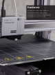
Hardware This chapter covers problems with the modules and addons of the Snapmaker 2.0, which includes the Enclosure, the Touchscreen, the 3D Printing Module, the Laser Module, and the Controller. For problems regarding the Snapmaker Luban, go to the next chapter.
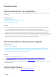
Hardware Touchscreen Touchscreen Shows "not responding" The Touchscreen shows the machine isn't responding, would you like to reconnect. This can happen pre- and mid-printing. Possible Causes • The Controller is broken. • The Touchscreen cable is connected wrongly. • The Touchscreen itself is broken. Actions 1. Check the condition of the light at the backside of the Controller. Normally it should be breathing steadily. - If it's not breathing, the Controller might have an issue.
Possible cause • The Touchscreen might be broken. Action Replace the Touchscreen. Touchscreen Is Black The Touchscreen is black and won't light up. Possible Causes • The Touchscreen itself is broken. • The Controller is broken. • The Power Module or DC power cable is broken. Actions 1. Check whether the light at the back of the Controller is breathing. - If it breathes slowly, launch Snapmaker Luban, and try to connect your computer with the machine using a USB cable.
Hardware - If the test values are normal, then the Power Module and the DC power cable are fine, and the Controller is the problem. In this case, replacing the Controller might solve the problem. - If the values are not normal (pin 1 and pin 4 is 0 V or 3 V, for example), then replacing the Power Module and DC power cable might solve the problem.
Linear Module Clunk Sound While Y Axes Are Moving Possible Cause • The two Y axes are not in sync. Actions 1. Swap one of the Y axes with the X axis. In most cases, the issue should be solved. 2. If the issue still exists, swap one Y axis with one of the Z axes. Linear Module Burns out Suddenly Possible Cause • The Linear Module is broken. Actions Replace the Linear Module. Linear Module Only Moves in One Direction Possible Cause • The end-stop switch is stuck. Actions 1.
Hardware 3. Fix the end-stop switch on your TRIGGERED Linear Module. 3.1 Disassemble the cover (the one with no cable end) of the Linear Module. You will need the 2.5 & 2.0 hex screwdriver. 3.2 Find the end-stop switch. Check if it's stuck. 3.3 Tap the end-stop switch and re-assemble the Linear Module. 4. Check if the Linear Module works. If not, replacing the Linear Module might solve the problem. Slider (Carriage) of Linear Module Comes Loose Actions 1.
2. Slide the Slider off from the Linear Module. Note: One side of the bearings is adjustable.
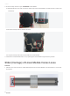
Hardware 3. Loosen the screw circled in the picture below. 4. Twist the bearing screw with an H3 hex screwdriver to adjust the distance between the bearings of two sides. The distance should be 34.29 mm. 5. Tighten the fastening screw first and then tighten the bearing screw. 6. Repeat step 3 to 5 to adjust the other bearing. 7. Re-assemble the Linear Module.
Stainless Steel Strip of Linear Module Comes Loose Actions Please refer to the video on installing the stainless steel strip of the Linear Module at https://drive.google.com/ file/d/1tUFob6tJCzQmuNlBeBNeBUayOdsDXi4W/view?usp=sharing.
Hardware 3D Printing 3D Printing Module Isn't Detected If you turn on the machine, and the Touchscreen displays an error message Snapmaker tech-team, then it might be that the 3D Printing Module is not detected by the machine. Possible Causes • The toolhead cable is broken. • The Linear Module or the Controller is broken. • The 3D Printing Module is broken. Actions 1. Replace the current toolhead cable with one of the interchangeable cables (see picture below).
2. Remove all the cables of the Linear Modules from the Controller, and see if the Printing Module, Laser Module, and CNC Module can be detected. - If yes, then it means one or more Linear Modules are disrupting Controller Network Area (CAN) communication. Reconnect cables of each Linear Module one by one to the Controller, and identify which Linear Module(s) is broken. - If no, then the Controller itself might be broken, replacing it might solve the problem. 3.
Hardware 2. In Luban, go to Printing Settings to set the Initial Layer Print Speed as 8 mm/s and try again. 3. Try another filament. 3D Printing Module Pushes into Print Sheet The 3D Printing Module clashes against the Print Sheet during calibration or printing. Possible Causes • The Y axes are not assembled properly. In this case, the 3D Printing Module is likely to clash against the Print Sheet at the first or the fifth calibration point.
2. Check whether the screws on the aluminum grid platform face downward as illustrated. If not, re-install all the screws on the platform. 3. If the problem persists, check whether the probe sensor is working properly. For detailed instructions, see Adjustprobe/proximitysensor of 3DPrinting Module. 4. If the problem persists, check the condition of probe sensor wiring. Open the right cover of the Printing Module and find the sensor wiring. Unplug it and then plug it back in. Close the cover and try again.
Hardware Possible Causes • The filament switch is broken. Actions 1. Remove the fan: https://youtu.be/e2L_Y_HZGgA. 2. Adjust the filament switch: https://youtu.be/_KAQvMNoJUQ. Filament Won't Load Possible Causes • The nozzle is jammed. • The filament is bent or compromised. • The 3D Printing Module or Controller is broken. Actions 1. Replace the hot end. A spare hot end is included in the box. For how to change the hot end, see https://drive.google.com/file/d/16lLntfp-3V-j48pP_-aeRtADg49mSnek/view. 2.
4. On the Touchscreen, go to Control > Nozzle. 5. Wait for the nozzle to heat up until you can tap the Load or Unload button. Make sure the nozzle temperature matches the working temperature of the filament you are using (ABS generally requires a higher temperature than PLA, for example). Tap Load to see if the gear inside the 3D Printing Module rotates. - If it does, then use a metal stick to poke the feeding hole (see picture below). Make sure the filament inside is all cleaned up.
Hardware - If it doesn't, then check whether the Laser Module works. - If the Laser Module works well, then the Printing Module itself is broken, replacing it might solve the problem. - If the Laser Module won't emit blue laser light (or won't stop emitting it, for that matter), then something is wrong with the Controller. It might be that the customer has connected the toolhead cable in the wrong direction, and the Controller and the cable is damaged as a result. Replace the Controller.
Actions 1. Replace the hot end before trying any of the following steps. A spare hot end is included in the box. For how to change the new hot end kit, see https://youtu.be/2anRrb_R63o. Note: If it's hard to remove the blobs from the current hot end, heat the nozzle up to 230 ℃ and try again. 2. Lower the printing speed. In Luban, go to Printing Settings > Click + > put in lower values in Speed. 3. Recalibrate. For detailed instruction on calibration, refer to the Quick Start Guide. 4.
Hardware Touchscreen Shows a -30 ℃ Nozzle Temp Possible Causes • The thermistor is dislocated. • The hot end is broken. Actions 1. Check if the thermistor (see circled in picture below) is securely seated in the hole. Plug it back in if it is not. If the problem persists, try the next step. 2. Replace the hot end. For how to replace the hot end, see https://drive.google.com/file/d/16lLntfp-3V-j48pP_-aeRtADg49mSnek/view.
2. If the problem persists, replacing the 3D Printing Module might solve the problem. Heated Bed Won't Heat up The Heated Bed won't heat up when you set the target temperature on the Touchscreen or when you start a print. Possible Causes • The cable of the Heated Bed is broken. • The thermistor of the Heated Bed is open- or short-circuited. • The Heated Bed is open-circuited. • The Heated Bed port on the Controller is broken. Actions 1.
Hardware 2. Get a multimeter, unplug the Heated Bed cable from the Controller, and measure the resistance of the Heated Bed. The resistance should be in the range of 60 KΩ – 130 KΩ. If the test value is out of the range, then the Heated Bed might be broken, replacing it might solve the issue. 3. Check if the circuit is open. Get a multimeter, set it to continuity, and test the two big pins (see picture below) inside the connector of Heated Bed cable.
3D Printing Module Clashes against the Print Sheet during Calibration Possible Causes • You are using an old version of the firmware. • The sensor isn't seated right. Actions 1. Download and install the latest version of firmware from https://forum.snapmaker.com/t/snapmaker-2-0-firmware-updates-and-downloads/5443/12. See if this solves the problem. If not, follow the steps below to test your probe sensor. 2. Start auto-calibration on the Touchscreen.
Hardware 4.3 Loosen the screw of the probe sensor so that it can be adjusted. 4.4 Find a credit card (or anything with a height of about 1 mm). Move the module down until the nozzle tip touches the Print Sheet; then put the card under the probe sensor so that the sensor is approximately 1 mm higher than where the nozzle tip is. 4.5 Tighten the screw of the probe sensor. 4.6 Reassemble the 3D Printing Module correctly.
4.7 Redo calibration following the prompts on the Touchscreen. Keep the machine connected to the computer the whole time.
Hardware Laser Laser Calibration Fails If the Laser Calibration doesn't go well, the Touchscreen will display Failed. Possible Causes • The laser is too high. Actions Two options are available. 1. Redo auto focus. Tap Failed, slide the scale left to select the leftmost line, and tap Save. The screen should go back to the main menu. Tap Calibration. If the problem persists, repeat the steps until calibration succeeds.
2. Change the Laser Height manually. On the Touchscreen, tap Failed > Settings > Laser > Adjust Laser Height. Set the Laser Height to 23.0mm and then recalibrate. If the Touchscreen keeps showing Failed, and several lines fail to be burned, then lower the laser height (to 21.5 mm or 19 mm, for example), and try again. Laser Is Discontinuous Or Weak The Laser Module emits weak light and doesn't engrave at its full power, and therefore the module can't finish Auto Focus.
Hardware 3. If the problem persists after you have tried the options above, and your built-in camera can't find the finest line while auto focusing (see picture below), then the Laser Module should be replaced. Machine Is Stuck in Processing during Auto Focus During auto focus, the machine is stuck in the Processing screen (see picture below) and won't finish the process. Possible Cause • The laser shade is impeding auto focus.
Camera Capture Doesn't Work If the image isn't fully processed, it indicates that camera capture isn't working properly. Possible Causes • Your Snapmaker Luban is running the old version. • You are not using camera capture correctly. Actions 1. Download the latest version of Snapmaker Luban from https://snapmaker.com/product/snapmaker-2/downloads. 2. Watch the tutorial at https://www.youtube.com/watch?v=cult_7nTTpk&t=10s. Or, follow the steps below. 2.
Hardware 2.2 Click Start to see if it works properly. 2.3 If the camera capture feature still doesn't work, please find the images generated by the camera through the following path. Export them to your USB drive, and send them to support@snapmaker.com for further investigation. - Windows OS: C:\Users\admin\AppData\Roaming\snapmaker-luban\Tmp - macOS: /Users/admin/Library/Application\ Support/snapmaker-luban/Tmp Note: admin is your username.
Laser Module Doesn't Emit Laser Possible Causes • The laser is disabled. • The Controller is broken. Actions 1. On the Touchscreen, go to Control > Laser Power > Laser Status to turn it on. See if blue laser light comes out. If not, go to step 2. 2. Find out which one is the problem first. Get your 3D Printing Module, turn on the machine, and press to open the latch on the 3D Printing Module. 3. On the Touchscreen, tap Control > Nozzle.
Hardware 4. Wait for the nozzle to reach 200 ℃ , tap Load or Unload, and see if the gear in the module rotates. - If it does, then change the toolhead cable. - If it doesn't, then the Controller is broken. It might be that the customer has connected the toolhead cable in the wrong direction, and the toolhead and the Controller is damaged as a result. You will need to first replace the Controller. Then, check if the 3D Printing Module and Laser Module works with the new Controller.
Camera Sign Is Yellow on Touchscreen When the camera sign on the Touchscreen is yellow, it means that the camera isn't working properly. Possible causes • Something is wrong with the Touchscreen's settings. • The toolhead cable is broken. Actions 1. Reset the Touchscreen. 1.1 Tap Settings > About Machine.
Hardware 1.2 Tap the image five times and the Touchscreen will prompt you to Enter Developer Mode. Tap OK. 1.3 Under Developer Mode, tap Experiment > Preference > Reset All. See if this solves the problem. If not, go to step 2.
2. Replace the current toolhead cable with one of the interchangeable cables (see picture below). See if this solves the problem. If not, then the Laser Module is broken and needs to be replaced. Toolhead Cable Y Conversion Cable Z Conversion Cable Laser Won't Turn off The blue laser light of the Laser Module turns on and can't be turned off via the Touchscreen or Snapmaker Luabn. Possible Causes • The Toolhead cable is broken. • The Laser Module or the Controller is broken. Actions 1.
Hardware 2.2 On the Touchscreen, go to Control > Nozzle. 2.3 Wait for the nozzle to heat up until you can tap Load or Unload. Tap Load to see if the gear inside the 3D Printing Module rotates. - If it does, then the Laser Module might be broken, replacing it might solve the problem. - If it doesn't, then something is wrong with the Controller. Go to step 3. 3. Judging by similar cases, the most possible reason is that the toolhead cable connector was plugged in wrongly.
- You will need to first replace the Controller. Then, check if the 3D Printing Module and the Laser Module work properly with the new Controller. If not, these modules may also be broken and need to be replaced. Laser Won't Burn Material When Enclosure Is Used Possible Cause • The door of the Enclosure is open when the Laser Module is working. Actions Close the enclosure doors before you start to use the Laser Module.
Hardware Enclosure Enclosure Isn't Detected Or Recognized The Enclosure of Snapmaker 2.0 isn't recognized by the machine. That is, when it's connected to the machine, there is no Enclosure icon on the Touchscreen. Possible Causes • The firmware is outdated. • The Converter of the Enclosure is broken. • The Hall switch is broken, which could result in Enclosure being recognized while the switch is not connected to the Converter, and vice versa, when it's supposed to act the other way around.
4. Unplug the enclosure cable from the Converter while the other end remaining connected to the Controller. Turn on the machine. Set the multimeter to voltage mode and test the two big pins. The normal value should be 24 V. 5. Test the GND & pin 1, and then test the GND & pin 2 (see below) respectively. The test results should both be 2.2 V. If any of the test results in step 4 or 5 is abnormal, then the Controller is broken. Replacing it might solve the problem.
Hardware Others Power Module Doesn't Work The Power Module is unresponsive when turned on. The LED light won't flash, and the fan won't turn. Possible Causes • The voltage is out of working range. • The AC cable is broken. • The Power Module is broken. Actions 1. Make sure the input voltage falls into the range between 88–264 V AC, and the output voltage is 24 V. 2. Use another AC cable to test the module. The AC cable is universal.
Machine Can't Detect USB Drive Possible Causes • The file system of the USB drive isn't compatible with that of the machine. • The capacity of the USB drive is too big. • The USB drive is broken. • The G-code file's suffix is incorrect. • The USB port on the Touchscreen is broken. Actions 1. Check if your G-code file end with .gcode when the machine is connected to the 3D Printing Module. Similarly, the G-code file should end with .nc and .
Hardware 5. Turn off the machine and plug in another toolhead cable to repeat step 3 and 4 until you have tested all the toolheads. - If the problem persists, please contact us with the results and a recorded video via email. - If the toolheads can be detected, then the problem is with the Linear Modules or the port on the Controller. 6. Turn off the machine, and plug in the cable of each Linear Modules into the axes ports on the Controller, one at a time. See if they can be detected.
Software The Snapmaker Luban is still a young software, compared with many of its counterparts. And as with every software, Snapmaker Luban isn't perfect. The troubleshooting in this chapter is helpful in solving preliminary issues, and you should follow them first. If the problem persists, please contact us at support@snapmaker.com. In the meantime, we would appreciate that you file an issue on our GitHub page: https://github.com/Snapmaker/Luban. Your feedback will motivate us to do better.
Software Luban Won't Generate G-code File The Snapmaker Luban fails to generate G-code files. The progress bar gets stuck. Possible Causes • This is an old version of Luban. • There is a bug in the software. • The file is too large to be parsed. Actions 1. Download and install the latest version from https://snapmaker.com/product/snapmaker-2/downloads. 2. Restart or reinstall the Snapmaker Luban. 3. Try a smaller G-code file that is less than 100 MB.
5. Launch the Snapmaker Luban, select the correct port and try again. Luban Is Blank upon Launched The Snapmaker Luban goes blank right after you launch it, and only the menu bar on the top-left corner is available. Actions 1. Reload Snapmaker Luban. On the menu bar, click View > Reload (or press Ctrl + R) to reload Luban. 2. Download and install the latest version from https://forum.snapmaker.com/t/snapmaker-2-0-firmware-updates-and-downloads/5443/12. See if this solves the problem.
Software 4. Re-install Snapmaker Luban, and try again. 5. If the problem persists, then proceed to test Snapmaker Luban in your browser. - Launch Snapmaker Luban. - On the Menu, click View > View In Browser. Luban will be opened by your browser. 6. If the problem persists, then proceed to track information with the Developer Tool. Launch Luban, and then press Ctrl + Shift + I keys at the same time to access the Developer Tool. Click Console, and screen capture the error messages.
Luban Shows "The machine is not ready" When trying to connect the machine to the Snapmaker Luban, it shows The machine is not ready or cannot open the port. Possible Causes • You haven't installed the CH340 driver. • You attempted to connect to the wrong port. Actions 1. Download and install the CH340 driver from https://snapmaker.com/product/snapmaker-2/downloads. 2. Find the correct port following the steps below. Then launch Luban and try again. 2.
Software No Camera Capture Button in Luban Possible Cause • You are using the USB cable to connect the machine to Luban (camera capture can only be accessed via Wi-Fi connection). USB Cable Action Connect the machine with Luban via Wi-Fi instead, and you will be able to use camera capture.
Appendix | 47
Appendix Parts List 3D Printing Module Laser Module CNC Module Controller Touchscreen Heated Bed Linear Module Print Sheet | A350 QUICK START GUIDE MAKE SOMETHING WONDERFUL Power Module Quick Start Guide Fixture Accessory Touchscreen Holder Converter Filament Holder Sheet Filament Holder Tube Arched Fixture Laser Safety Goggles Toolhead Cable 48 | Filament CNC Safety Goggles Y Conversion Cable Z Conversion Cable Material Bag CNC Carving Platform Z-Axis Holder Laser Engraving/Cut
Tool Box M4 x 30 Screw M4 x 10 Hex Socket Head Screw M4 x 8 Screw M4 x 10 Hex Flat Head Screw M4 x 70 Screw Wing Nut Foot + M4 x 10 Hex Socket Head Screw ER11 Collet (Only for 3.
Appendix Specs Sheet Snapmaker 2.0 General The maximum length of the support platform of the Snapmaker 2.0 A150 model is 360 mm. The maximum length of the support platform of the Snapmaker 2.0 A250 model is 580 mm. The maximum length of the support platform of the Snapmaker 2.0 A350 model is 660 mm.
Frame Material Aluminum Alloys Connectivity Wi-Fi, USB Cable, USB Flash Drive Touchscreen 5”, Android OS, Quad Core A7 CPU @ 1.1 GHz Software Snapmaker Luban. You can also use third party software to generate G-code files.
Appendix Laser A150 A250 A350 Camera Built-in Camera Laser Power 1600 mW 450 nm Laser Diode Wavelength 450 nm Safety Class Class 4 Supported Materials Wood, leather, plastic, fabric, paper, non-transparent acrylic, more being tested 52 | Design File Formats .svg, .jpeg, .png, .jpg, .bmp, .dxf, .snaplzr Processable Format .
CNC A150 A250 A350 Shank Diameter 0.5 mm–6.35 mm (0.02–0.25 inches) Spindle Speed 6,000–12,000 RPM Supported Materials Wood, acrylic, PCB, carbon fiber sheet, jade, more being tested Design File Formats .svg, .jpeg, .png, .jpg, .bmp, .dxf, .snapcnc Processable Format .cnc Note: The specifications are subject to change without notice.
Hardware Publication Date: February 10, 2021 54 |