PV Mounting System 2703 SERIES 200 UL GROUND MOUNT SYSTEM SnapNrack Solar Mounting Solutions Code Compliant Installation Manual
Introduction Series 200 UL Residential Ground Mount Series 200 UL Introduction SnapNrack Series 200 Ground Mount System offers a low profile, visually appealing, photovoltaic (PV) module installation system. This innovative system simplifies the process of installing solar PV modules, shortens installation times, and lowers installation costs.
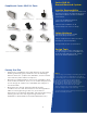
Series 200 UL Ground Mounted System SnapNrack Series 200 UL Parts Installer Responsibility -Make sure that the SnapNrack components and other products are appropriate for the particular installation and the installation environment. SnapNrack Ground Rail SnapNrack Pipe Clamp Assembly SnapNrack Adjustable X-End Clamp Assembly - Use only SnapNrack supplied parts for the rail system. - Ensure safe installation of all electrical aspects of the PV array.
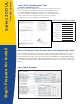
Survey& Layout Series 200 UL Series 200 Configuration Tool configure.SnapNrack.com Once you have calculated the specs for you system, you can enter the data into SnapNrack’s online Configuration Tool for Series 200 Ground Mount System. The Configuration Tool creates a Bill of Materials specific to your system which can be exported as a separate file for you to use when contacting your local SnapNrack distributor. Project Information Section Array Tilt Angle Wind Speed Snow Load Topo. Cond.
Series 200 UL Ground Mounted System Layout Your System Typically most ground mounted arrays are installed in a landscape configuration, with the long side of the PV modules horizontal and the rails running up the slope. This is different from roof mount installations which typically are in a portrait configuration with the long side of the module running up slope and the rails running horizontally. Notes - Module mid clamps are installed between modules in a row and require 0.
Concrete Pier Series 200 UL Step 2: Excavation & Pipe Installation Required Tools: 12” diameter Excavation Drill Auger Portable Band Saw (18 tpi) Concrete Mixer Basic Concrete Tools String Line Surveying Marker Pen or Paint Materials Needed for Concrete Pier Install: Sched 40 or 80 1-1/2” Pipe w/ 1.
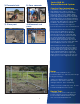
1) Excavate hole 2) Pour concrete Series 200 UL Ground Mounted System Step-by-Step Instructions 3) Place post 4) Measure & cut posts 1) Prepare to excavate holes by measuring and staking hole locations. Set first stake and run a string perpendicular to true South and set second stake. Stake remaining corners of the array according to the plan layout. Excavate core footings at marked location to the depth indicated in your state’s Engineering Letter.
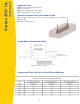
Grade Beam Series 200 UL Required Tools: Backhoe tractor with 12” Bucket Concrete Mixer Basic Concrete Tools String Line Surveying Marker Pen or Paint Materials Needed for Grade Beam Install: Sched 40 or 80 1-1/2” Pipe w/ 1.
12” Wide Grade Beam Footing Option Series 200 UL Ground Mounted System Step-by-Step Instructions 1) Prepare to excavate grade beams by measuring and staking hole locations. Set first stake and run a string perpendicular to true South and set second stake. Stake remaining corners of the array according to the plan layout. Excavate grade beams at marked location to the depth indicated in your state’s Engineering Letter. Grade beam size may vary depending on jobspecific conditions.
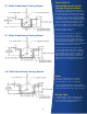
Standard Bracing Series 200 UL Required Tools: Allen Wrench Portable Band Saw Measuring Tape Materials Needed for Standard Bracing Install: Sched 40 or 80 1-1/2” Pipe (Local Supplier) Single Socket Tee End Caps Galvanized Spray Step 3: Bracing Options Socket Tee to Post 10 Horizontal Pipes with Bracing
1) Slide all brace fittings onto posts 2) Install socket tees Series 200 UL Ground Mounted System Step-by-Step Instructions 1) Determine the necessary cross bracing and required structural fittings before horizontal pipes are installed. Slide all fittings onto vertical pipes to meet bracing plan. If needed, cross bracing will be specified on the plans and in the BOM (needed if verticals are over 5’). 2) Determine the required number of single socket tees and slide onto the horizontal pipes.
Braced Option Series 200 UL Required Tools: Allen Wrench Portable Band Saw Measuring Tape Materials Needed for Standard Bracing Install: Sched 40 or 80 1-1/2” Pipe (Local Supplier) Single Socket Tee Swivel Socket Tee End Caps Galvanized Spray 12
1) Slide all brace fittings onto posts 2) Install socket tees Series 200 UL Ground Mounted System Step-by-Step Instructions 1) Determine the necessary cross bracing and required structural fittings before horizontal pipes are installed. Slide all brace fittings onto vertical pipes. If needed, cross bracing will be specified on the plans and in the BOM (needed if verticals are over 5’). 2) Determine the required number of single socket tees and slide onto the horizontal pipe.
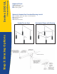
Installing and Leveling Rails Series 200 UL Required Tools: Level String Line or Spare Rail Pitch Meter 1/2” Socket Wrench 5/32” Allen Key Torque Wrench Materials Needed to Install Rails: Ground Rail Pipe Clamp Assemblies Step 4: Rail Installation Pipe Clamp to Rail Assembly Materials Included In Wire Clips: (1) SnapNrack Wire Clip Dimensioned Wire Clip 14
1) Determine rail layout Pipe Clamps Torque: 12ft-lbs Series 200 UL Ground Mounted System 2) Place pipe clamps & rails Step-by-Step Instructions 1) Find center of array and mark edges of each module on the lower horizontal pipe. Determine the distance from the lower horizontal to the edge of the rail. Mark all rails at this distance. 2) Place pipe clamps on horizontal rails where markings are placed. Next, place rails where markings are placed.
Attaching Modules Series 200 UL Required Tools: 1/2 inch Socket Wrench Torque Wrench Materials Needed to Install Mid & End Clamps: Pre Installed SnapNrack Pipe Structure Attachments Pre Installed SnapNrack Rails SnapNrack Mid Clamp Assemblies SnapNrack End Clamp Assemblies PV Modules Step 5: Module Installation Mid Clamp Assembly: (1) 5/16in - 18 X 2 1/2in SS HCS Bolt (1) 5/16in SS Split Lock Washer (1) SnapNrack Mid Clamp (1) 5/16in - 18 SnapNrack Bonding Channel Nut X Clamp As
SnapNrack Mid Clamp 1) Snap into channel Torque: Silver 10-16 ft-lbs. Black 8-10 ft-lbs. 2) Set mid clamp & modules Series 200 UL Ground Mounted System Step-by-Step Instructions SnapNrack Mid Clamp 1) Snap the preassembled SnapNrack Mid Clamp’s channel nut into the top channel of the rail. 2) Slide the mid clamp flush to the module with the top lip of the mid clamp over the top edge of the module. Place the next module flush to the other side of the mid clamp.
System Ground Series 200 UL Step 6: System Ground System Ground Methods Include: SnapNrack Bonding Lug Ilsco Bonding Lug UL 2703 Listing ensures that all components in the system include modules are bonded when a sysem ground is properly installed. 1 system ground is required per individual array section.
Series 200 UL Ground Mounted System SnapNrack Bonding Lug 1) Snap in Bonding Lug 2) Attach grounding Step-by-Step Instructions SnapNrack Bonding Lug 1) Snap in the SnapNrack Bonding Lug in to the rail channel. 2) Attach grounding conductor into slot and tighten bolt to 7 ft-lbs. 3) Tighten all hardware to a min of 10 ft-lbs.
Series 200 UL Notes 20