Operator’s Manual SW20 Series R N ep o ro t fo du r ct io n Walk-Behind Mowers Model Number: 5900700 5900702 5900757 5900965 5900539 Description SW20KAV1748, 48” Cut Walk-Behind Mower SW20KAV1336, 36” Cut Walk-Behind Mower SW20BV1648, 48” Cut Walk-Behind Mower SW20KAV1636, 36” Cut Walk-Behind Mower SW20KAV1536, 36” Cut Walk-Behind Mower This manual is available in Spanish. For a copy, contact your Snapper Pro dealer or www.snapperpro.com. Este manual está disponible en Español.
Thank you for purchasing this quality-built SNAPPER PRO product. We’re pleased that you’ve placed your confidence in the SNAPPER PRO brand. When operated and maintained according to the instructions in this manual, your SNAPPER PRO product will provide many years of dependable service. This manual contains safety information to make you aware of the hazards and risks associated with this machine and how to avoid them.
Table of Contents R N ep o ro t fo du r ct io n Operator Safety ...........................................................2 Safety Rules and Information ...........................................2 Safety Decals ....................................................................8 Safety Interlock System ....................................................9 Features & Controls ..................................................10 Identification Numbers ...................................................
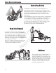
Safety Rules & Information Operating Safety Congratulations on purchasing a superior-quality piece of lawn and garden equipment. Our products are designed and manufactured to meet or exceed all industry standards for safety. Do not operate this machine unless you have been trained. Reading and understanding this operator’s manual is a way to train yourself. Power equipment is only as safe as the operator.
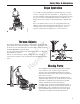
Safety Rules & Information Slope Operation You could be seriously injured if you use this unit on too steep of a slope. Using the unit on a slope that is too steep where you do not have adequate footing and unit traction (and control) can cause you to lose control and possibly slip and fall or roll the unit over. Always mow across slopes, not up and down (you could slip and fall.) Also, note that the surface you are on can greatly impact your ability to safely operate this machine.
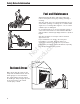
Safety Rules & Information Fuel and Maintenance Always disengage all drives, shutoff the engine and remove the key before doing any cleaning, refueling or servicing. Gasoline and its vapors are extremely flammable. Do not smoke while operating or refueling. Do not add fuel while engine is hot or running. Allow engine to cool for at least 3 minutes prior to adding fuel. Do not add fuel indoors, in an enclosed trailer, garage or other enclosed area that is not well ventilated.
Safety Rules & Information Read these safety rules and follow them closely. Failure to obey these rules could result in loss of control of unit, severe personal injury or death to you, or bystanders, or damage to property or equipment. This mowing deck is capable of amputating hands and feet and throwing objects. The triangle in text signifies important cautions or warnings which must be followed. TRAINING PREPARATION R 1.
Safety Rules & Information 23. Use care when approaching blind corners, shrubs, trees or other objects that may obscure vision. 24. To reduce fire hazard, keep unit free of grass, leaves & excess oil. Do not stop or park over dry leaves, grass or combustible materials.
Safety Rules & Information SERVICE AND MAINTENANCE To avoid personal injury or property damage, use extreme care in handling gasoline. Gasoline is extremely flammable and the vapors are explosive. N ep o ro t fo du r ct io n Safe Handling of Gasoline 1. Extinguish all cigarettes, cigars, pipes, and other sources of ignition. 2. Use only approved gasoline containers. 3. Never remove the gas cap or add fuel with the engine running. Allow the engine to cool before refueling. 4.
Operator Safety Safety Decals Before operating your unit, read the safety decals. The cautions and warnings are for your safety. To avoid a personal injury or damage to the unit, understand and follow all safety decals. 1 WARNING If any safety decals become worn or damaged, and cannot be read, order replacement decals from your local dealer. 2 3 N ep o ro t fo du r ct io n 4 4 1 R 5 2 2 5 3 8 3 www.SnapperPro.
Operator Safety Safety Icons Safety Interlock System This unit is equipped with safety interlock switches. These safety systems are present for your safety, do not attempt to bypass safety switches, and never tamper with safety devices. Check their operation regularly. Operational SAFETY Checks Test 1 — Engine should NOT crank if: • PTO switch is engaged, OR • Parking brake is not engaged, OR • Forward speed control lever is not in the NEUTRAL position.
Features and Controls Features and Controls Identification Numbers SA M North American Models PL E SA Model xxxxxxx xxxxxxxxxxxxxxxxxxxx Serial xxxxxxxxxx M PLXXX E BRIGGS & STRATTON CORP. POWER PRODUCTS GROUP, LLC MILWAUKEE, WI 53201 USA 20xx CE Models kg: xxx kW: x.xx xxxx max A Figure 1. Identification Numbers A. Identification Tag N ep o ro t fo du r ct io n When contacting your authorized dealer for replacement parts, service, or information you MUST have these numbers.
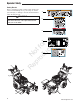
N ep o ro t fo du r ct io n Features and Controls Figure 2. Control Locations Control Functions R The information below briefly describes the function of individual controls. Starting, stopping, driving, and mowing require the combined use of several controls applied in specific sequences. To learn what combination and sequence of controls to use for various tasks see the OPERATION section. Forward Speed Control Lever Reverse Speed Control Levers These levers control the ground speed of the mower.
Features and Controls Parking Brake Fuel Tank Cap DISENGAGE Releases the parking brake. ENGAGE Locks the parking brake. Pull the parking brake handle up to engage the parking brake. Push the parking brake handle down to disengage the parking brake. NOTE: To start the unit the parking brake must be engaged. To remove the cap, turn counterclockwise. Engine Kill / Operator Presence Handles These handles are a major factor in the safety interlock system of the mower.
Operation Operation A General Operating Safety Before first time operation: • Be sure to read all information in the Safety and Operation sections before attempting to operate this unit. • Become familiar with all of the controls and how to stop the unit. • Drive in an open area without mowing to become accustomed to the unit. Checks Before Starting C Figure 3. Pre-start Checks A. Fuel Tank Filler Neck B. Engine Oil Dipstick C. Hydraulic Oil Fill Starting the Engine 1.
Operation Stopping the Mower 1. Gently squeeze both reverse speed control levers evenly to stop the unit. 2. Once the unit is stopped, firmly depress the neutral return pedal to place the transmission in neutral. 3. Disengage the PTO by pushing down on the PTO switch. 3. Engage the parking brake by pulling the handle up until it locks into position. 4. Move the throttle control to mid-throttle position and turn the ignition key to OFF. Remove the key. Figure 4.
Operation Cutting Height Adjustment A The cutting height can be adjusted within two different ranges. The lower cutting range is adjustable between 1-1/2” (3,8 cm) and 2-3/4” (6,9 cm). The upper cutting range is adjustable between 2-3/4” (6,9 cm) and 4-1/2” (11,5 cm). Before adjusting the cutting height, you must first determine the average cutting height. Depending on the range you plan to use, it may be necessary to adjust which pulley the deck drive belt runs in. To Adjust the Cutting Range: 1.
Operation To Adjust the Cutting Height: The cutting range must be adjusted to the correct range before the cutting height can be adjusted. The cutting height indicators will help you identify the cutting height. D B 1. Pull the cutting height adjustment handle (A, Figure 10) up and out of the handle lock position (B) and crank the handle CLOCKWISE to raise the deck to the desired cutting height. Crank the handle COUNTER-CLOCKWISE to lower the deck to the desired cutting height.
Operation Driving The Mower Before attempting to drive the mower make sure you have read the Features and Controls section and understand the location and function of the controls. The hydrostatic transmission has an infinite number of speeds between full speed forward and reverse, with the faster speeds being achieved by moving the forward speed control lever and reverse speed control levers farthest in the direction of travel.
Operation Mowing Before mowing, set the cutting height as described in CUTTING HEIGHT ADJUSTMENT. 1. Engage the parking brake. Make sure the PTO switch is disengaged and the forward speed control lever is in the NEUTRAL position 2. Start the engine (see Starting The Engine). 3. Set the throttle to FULL. 4. Engage the PTO by pulling up on the PTO switch. 5. Begin mowing. See Mowing Recommendations for tips on mowing patterns, lawn care, and trouble shooting information. 6.
Operation When and How Often to Mow The time of day and condition of the grass greatly affect the results you’ll get when mowing. For the best results, follow these guidelines: 1. Mow when the grass is between three and five inches high. 2. Mow with sharp blades. Short clippings of grass one inch or shorter decompose more quickly than longer blades. Sharp mower blades cut grass cleanly and efficiently, preventing frayed edges which harm the grass. 3. Mow at time of day when the grass is cool and dry.
Operation Proper Mulching Mulching consists of a mower deck which cuts and recuts clippings into tiny particles and which then blows them down INTO the lawn. These tiny particles decompose rapidly into by-products your lawn can use. UNDER PROPER CONDITIONS, your mulching mower will virtually eliminate noticeable clippings on the lawn surface. NOTE: When mulching under heavy cutting conditions, a rumbling sound may be present and is normal.
Regular Maintenance Regular Maintenance Maintenance Schedule The following schedule should be followed for normal care of your mower and mower deck. You will need to keep a record of your operating time. Determining operating time is easily accomplished by observing the elapsed time recorded by the hour meter.
Regular Maintenance WARNING Checking / Adding Fuel To add fuel: Fuel and its vapors are extremely flammable and explosive. Fire or explosion can cause severe burns or death. 1. Remove the fuel cap (E, Figure 12). 2. Fill the tank to the bottom of the filler neck. This will allow for fuel expansion. NOTE: Do not overfill. Refer to your engine manual for specific fuel recommendations. 3. Install and hand tighten the fuel cap. Fuel Filter Change Oil & Filter R 1.
Regular Maintenance Lubrication Lubricate the unit at the locations shown in Figures 13 & 14 as well as the following lubrication points. Grease: • • • • front caster wheel axles & yokes deck lift pivot blocks mower deck spindles mower deck idler arm Use grease fittings when present. Disassemble parts to apply grease to moving parts when grease fittings are not installed. Not all greases are compatible.
Regular Maintenance Check / Fill Transmission Oil Oil Type: 20W-50 conventional detergent motor oil. 1. Check the oil level when the unit is cold. Locate the transmission oil reservoirs (A, Figure 15) located on the by the fuel tank. The oil should be up to the “FULL COLD” mark (B). If the oil is below this level, proceed to step 2. A 2. Before removing the reservoir caps, make sure the area around the reservoir cap and fill neck of the reservoir is free of dust, dirt, or other debris.
Regular Maintenance Servicing The Mower Blades Removing the Mower Blade CAUTION Avoid injury! Mower blades are sharp. Always wear gloves when handling mower blades or working near blades. 1. To remove the mower blade, use a 1” wrench on the flats of the spindle shaft and remove the mower blade mounting bolt with a 15/16” wrench (Figure 17). 2. If there are no flats on the spindle shaft, wedge a wooden block between the mower blade and the mower deck housing to keep the mower blade from turning. Figure 17.
Regular Maintenance Sharpening the Mower Blade A CAUTION Avoid injury! Mower blades are sharp. • Always wear gloves when handling mower blades or working near blades. • Always wear safety eye protection when grinding. Balancing the Mower Blades Figure 20. Sharpening the Mower Blade A. Mower Blade Bevel B. Mower Blade Cutting Edge N ep o ro t fo du r ct io n 1. Sharpen the mower blades with grinder, hand file, or electric blade sharpener. 2.
Regular Maintenance Neutral Adjustment If the unit “creeps” while the forward speed control lever is locked in the NEUTRAL position, then it may be necessary to adjust the linkage rod. A B NOTE: Perform this adjustment on a hard, level surface such as a concrete floor. 1. Disengage the PTO, engage the parking brake and turn off the engine. CAUTION This adjustment should not be performed while the machine is running. C B A Figure 23. Neutral Adjustment A. Ball Stud B. Nuts C.
Regular Maintenance (2014523388 & Above) B A R N ep o ro t fo du r ct io n To Reduce the Speed of the Faster Wheel: There are three (3) nuts (A, Figure 25) on the linkage rod (B). The first two are to be used together to turn the rod and the third is used to lock the rod in place. 1. Loosen the jam nut that locks against the clevis. 2. Turn the linkage rod COUNTER-CLOCKWISE to reduce the speed. 3. Retighten the jam nut when adjustment is complete. Figure 25. Adjusting the Speed of the Faster Wheel A.
Regular Maintenance Parking Brake Adjustment 1. Disengage the PTO, stop the engine, remove the ignition key, and engage the parking brake. 2. Locate the brake spring (A, Figure 26) underneath the rear of the machine. 3. With the parking brake engaged, measure the compressed spring length of the brake spring. The spring should be 2-3/8” (6,03 cm) when compressed. If not, position the lock nut until the measurement equals 2-3/8” (6,03 cm). 4.
Regular Maintenance Deck Leveling Adjustment A To Level the Mower Deck: 1. Park the machine on a flat, level surface. Disengage the PTO, stop the engine and engage the parking brake. Rear tires must be inflated to 15 psi (1,03 bar); front tires to 25 psi (1,72 bar). 2. Pull the cutting height adjustment handle (A, Figure 27) up and out of the handle lock position (B) and crank the handle CLOCKWISE and adjust the deck to the 3” (7,6 cm) position. 3. Repeat process for other side of machine.
Regular Maintenance Mower Belt Replacement D NOTICE C B To avoid damaging belts, do NOT pry belts over pulleys. 1. Park the unit on a smooth, level surface such as a concrete floor. Disengage the PTO, engage the parking brake, turn off the engine, and remove the ignition key. 2. Lower the mower deck to its lowest cutting position and remove the mower deck guard. 3. Using a 1/2” breaker bar (A, Figure 29), place the square end in the square hole located on the end of the idler arm (B).
Regular Maintenance Mower Belt Replacement (continued...) E D 5. Remove the old belt and replace with a new one. Make sure the V-side of the belt runs in the pulley grooves (Figure 30). 6. Install the mower drive belt on the PTO pulley, the spindle pulleys and all idler pulleys except the stationary pulley (C, Figure 29). Carefully rotate the breaker bar counter-clockwise and install the belt on the stationary idler pulley. Carefully release the tension on the breaker bar. 7.
Regular Maintenance Transmission Drive Belt Replacement 1. Park the unit on a smooth, level surface such as a concrete floor. Disengage the PTO, engage the parking brake, turn off the engine, and remove the ignition key. WARNING Spring loaded components can kick back causing injury. Improper release of the belt tension spring can result in personal injury. Use extreme caution when removing this spring. 2. Remove the PTO drive belt (see MOWER BELT REPLACEMENT for removal instructions). 3.
Regular Maintenance Reverse Speed Control Levers A Comfort Adjustment B The amount of pressure necessary to depress the Reverse Speed Control Levers (A, Figure 34) can be adjusted to meet the comfort needs of the operator. 1. Disengage the PTO, engage the parking brake and turn off the engine. 2. To increase the amount of pressure necessary to depress the Reverse Speed Control Levers turn the lock nut (B) CLOCKWISE until the desired comfort level is achieved.
Regular Maintenance Storage WARNING Temporary Storage (30 Days Or Less) Fuel and its vapors are extremely flammable and explosive. Fire or explosion can cause severe burns or death. Remember, the fuel tank will still contain some gasoline, so never store the unit indoors or in any other area where fuel vapor could travel to any ignition source. Fuel vapor is also toxic if inhaled, so never store the unit in any structure used for human or animal habitation.
Troubleshooting Troubleshooting Troubleshooting Chart WARNING While normal care and regular maintenance will extend the life of your equipment, prolonged or constant use may eventually require that service be performed to allow it to continue operating properly. The troubleshooting guide below lists the most common problems, their causes and remedies. See the information on the following pages for instructions on how to perform most of these minor adjustments and service repairs yourself.
Troubleshooting Mower Troubleshooting Continued. Problem Cause Remedy 1. 2. 3. 4. Transmission release lever(s) in “disengaged” position. Belt is broken. Drive belt slips. Brake is not fully released. 1. Move transmission release lever(s) to the “engaged” position. 2. See Drive Belt Replacement. 3. See problem and cause below. 4. See authorized service dealer 1. 2. Pulleys or belt greasy or oily. Tension too loose. 3. Belt stretched or worn. 1. Clean as required. 2. Adjust spring tension.
Troubleshooting Troubleshooting Common Cutting Problems Problem Cause Remedy Streaking. 1. 2. 3. 4. 5. 6. Blades are not sharp. Blades are worn down to far. Engine speed is too slow. Ground speed is too fast. Deck is plugged with grass Not overlapping cutting rows enough. Not overlapping enough when turning. 1. Sharpen your blades. 2. Replace your blades. 3. Always mow at full throttle. 4. Slow down. 5. Clean out the mower. 6. Overlap your cutting rows. 1. Roll or level the lawn. 2.
Specifications Specifications Note: Specifications are correct at time of printing and are subject to change without notice. Model Number ENGINE Make Model Displacement 5900700 5900702 5900757 5900965 5900539 17 Gross HP† Kawasaki 13 Gross HP† Kawasaki 16 Gross HP* Briggs & Stratton 16 Gross HP† Kawasaki 15 Gross HP† Kawasaki Kawasaki Kawasaki Briggs & Stratton Kawasaki Kawasaki FH541V FH381V 305776-0134-G1 FS481V-BS01-S FS541V-DS01-S 35.7 cu. in. (585 cc) 36.2 cu. in. (431 cc) 29.
40 2 ALIGN THIS EDGE WITH A VERTICAL SURFACE (TREE, POLE, FENCE POST, BUILDING, ETC) EGREE 3 COMPARE THE ANGLE OF THE FOLD TO THE ANGLE OF THE SLOPE 1. Fold this page along the dotted line indicated above. 2. Align the left edge of this guide with a vertical tree, a power line pole, a fence post, or any vertical structure. 3. Compare the angle of the fold with the angle of the hill.
N ep o ro t fo du r ct io n R Notes
N ep o ro t fo du r ct io n R Notes
N ep o ro t fo du r ct io n R
BRIGGS & STRATTON PRODUCTS WARRANTY POLICY September 2012 LIMITED WARRANTY Briggs & Stratton warrants that, during the warranty period specified below, it will repair or replace, free of charge, any part that is defective in material or workmanship or both. Transportation charges on product submitted for repair or replacement under this warranty must be borne by purchaser. This warranty is effective for and is subject to the time periods and conditions stated below.
California, U.S. EPA, and Briggs & Stratton Corporation Emissions Control Warranty Statement Your Warranty Rights And Obligations The California Air Resources Board, U.S. EPA, and Briggs & Stratton (B&S) are pleased to explain the emissions control system warranty on your Model Year 2012--2013 engine/equipment. In California, new small off-road engines and large spark ignited engines less than or equal to 1.0 liter must be designed, built, and equipped to meet the State’s stringent anti-smog standards.
Operator’s Manual SW20 Series R N ep o ro t fo du r ct io n Walk-Behind Mowers BRIGGS & STRATTON POWER PRODUCTS GROUP, LLC 5375 NORTH MAIN STREET MUNNSVILLE, NY 13409 800 933 6175