OPERATOR'S MANUAL 36”& 42 SNOW THROWER p . 36" SNOW THROWER T : MFG. NO. 1690033 : 42" SNOW THROWER MFG. NO. 1690032 CAUTION: Read Manual Thoroughly Before Operating PRINTED IN US.A.
Dear Customer: Congratulations on your selection and purchase of this snow thrower attachment. It has been carefully designed and constructed to give you years of dependable service. To ensure yourself of the utmost value and performance from this snow thrower, read this manual carefully. Be certain that your snow thrower is assembled, installed, and adjusted properly. For your protection, be sure that you (and anyone who will operate this machine) know how to use the machine safely.
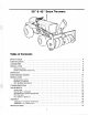
6” & 42” Snow Throwers | Table of Contents SAFETY RULES 2 IDENTIFICATION .. 4 ACCESSORIES .. 4 INSTALLATION 5 INSTALLATION 5 SNOW THROWER REMOVAL .. B OPERATION ...t in i ccanrcanannnsninovvnancnanns .. .7 MAINTENANCE RECORD .o NORMAL CARE ...t e crass ey cas v postconsonantal 11 SCHEDULED CARE sanction sy sonny 11 NORMAL STORAGE .. on OFF-SEASON STORAGE . o TROUBLESHOOTING 13 ADJUSTMENTS 14 SKID SHOE .. 14 DRIVE BELT TENSION .. 14 SCRAPER BAR DOWN PRESS o 14 CLUTCH .. .. 18 PTO SAFETY SWITCH . ..
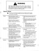
WARNING Read these safety rules and follow them closely. Failure to obey these rules could result in loss of control of vehicle, severe personal injury to yourself or bystanders, or damage to property or equipment affecting safety. sett e i Safety Rules This notation preceding Cautions and Warnings in the text signifies important precautionary steps which, if not properly follows, could result in personal injury or damage to your equipment affecting satiety.
@ If the unit should start to vibrate abnor® Be especially careful not to touch tractor mall, disengage PTQ, stop the engine, or attachment parts which might be hot and remove ignition key, and check from operation. Allow such parts to cool immediately for the cause. Vibration is before attempting to maintain, adjust, generally a warning of trouble. or service.
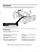
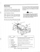
Identification When ordering replacement parts for your snow thrower, be prepared to give your dealer the identification number found on the identification plate shown below. We suggest you locate the number and record it here for easy reference. Refer toil. no. when writing or ordering parts. e SNOW THROWER IDENTIFICATION PLATE Accessories See your dealer t purchase any of the following accessories for your tractor or snow thrower.
Installation CONTENT OF SECTION This section guides you in installing the snow thrower on your tractor. It also provides instructions for removing the snow thrower from your tractor, INSTALLATION Before the snow thrower can be installed, it must first be completely assembled and the front PTO unit must be installed on your tractor. Procedures for assembly of these items are provided in the Assembly Section at the end of this manual.
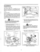
Installation A CAUTION For your personal safety, use care when installing belt on engine PTO pulley. If your foot slips off the idler pulley lever, the spring will tighten the belt and your fingers can be pinched at the PTO pulley. 6. Continue to hold idler pulley up while threading snow thrower V-belt over engine pulley. Be sure that V-belt is twisted as shown in figure 4. If belt seems short, idler pulley is not completely raised.
Operation CONTENT OF SECTION A brief description of the snow thrower controls, followed by the basic operating procedures, is given in this section to help you get to know your snow thrower and how to operate it safely and efficiently. SNOW THROWER CONTROLS Figure 5 shows the locations, names and functions of the snow thrower controls. The control names given in figure 5 are used throughout the manual. OPERATING PROCEDURES The rest of this section instructs you in the operation of your snow thrower.
Operation PREPARATION 1. Read this manual and the operator’s manual for your tractor carefully. Be sure you are familiar with the safety precautions, controls, and operating instructions. 2. Check the snow thrower carefully to be sure it is functioning properly. 8. Check the tires for proper inflation pressure: 20 1bs. psi (138 kPa) recommended for front tires when snow thrower is installed. 4. Refer to Normal Care section of this manual to determine and perform needed cave.
Operation The snow should be deposited beyond the surface you want to clear if at all possible. Start with the deflector all the way up so that the thrown snow is deposited just beyond the far side of the area to be cleared. Light to medium depth snow can be cleared using the full width of the auger on each pass, overlapping the passes a few inches to prevent side spillage.
Normal Care CONTENT OF SECTION Your snow thrower was guilt to provide years of service with only minor care.. These minor tasks, however, must be done to keep it in good operating condition and to avoid costly repairs. This section provides the necessary instructions for the care of your snow thrower. SCHEDULED CARE A schedule for normal, routine care is given in figure 7. This schedule is based on operating hours. To be sure that you meet the schedule, you will have to keep frack of operating hours.
Normal Care\ and belt. , Symbol Use Apply With Procedure . Lithium base automotive grease Grease Gun . Wipe fitting clean with rag, . Apply 2 or 3 shots of grease. . Wipe up any excess grease. oil Oil Can . Wipe mating parts clean. . Apply a few drops of oif on mounting pin or spout pivot surface, NN —q Figure 8. Lubricate Snow Thrower (10 Hour Care} THESE SPROCKETS MUST BE ALIGNED | st bobby 1. Remove two nuts and lock washers that secure | chain guard. 2, Remove chain guard. 3.
Troubleshooting CONTENT OF SECTION This section of the manual provides troubleshooting instructions for the more common and easily corrected snow thrower problems. For other problems, it is recommended that you contact your dealer. A WARNING To avoid serious injury, perform maintenance on the tractor or snow thrower oily when the engines stopped. Always remove the ignition key before beginning maintenance to prevent accidental starting of the engine.
Adjustments CONTENT OF SECTION This section contains adjustment procedures for the snow thrower and the front PTO that is used to power the snow thrower. ADJUSTMENT PROCEDURES WARNING To avoid serious injury, perform adjustment procedures on the tractor only when the en fine is stopped.
Adjustments PTO CLUTCH The front PTO clutch must be adjusted for proper operation. To check the adjustment, measure the distance between the thrust washer (item ¥, figure 18) and the bearing (item G) while the PTO lever is in the disengaged position. Then repeat the same measurement with the PTO lever in the engaged position. The difference between the two measurements should be 1/8 inch (8 mm). If not, adjust the PTO lute as follows: 1. Be sure that front PTO clutch lever is in engaged position. 2.
Assembly CONTENT OF SECTION The snow thrower is shipped only partially assembled for packaging reasons. This section provides the nec ry instructions for assembling the snow thrower and for installing the front PTO on the tractor. The instructions are the same for both the 36" and 427 snow throwers, SNOW THROWER ASSEMBLY Remove all loose parts, the skin pack, and the snow thrower from the shipping carton. Open the skin pack and hardware bags and arrange all parts according to size and type.
Assembly 7. Place the looped end of the cable over the stud on the spout extension {see figure 16). Place the small flat washer provided on the stud. Pull the other end of the cable around the stud as shown with a pliers. While holding the cable tight, install the cup washer (facing inward), lock washer and nut to hold the cable. Tape any loose cable neatly to the taut cable. NOTE The outer points of the special hex lock washers must face in toward the deflector to grip the flat surface.
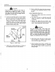
Assembly A WARNING For your personal safety, stop engine, set parking brake, and shift into neutral. Then raise tractor hood and remove spark plug wire and fasten il away from engine. 1. The key way in engine crankshaft {see figure 20} must be straight up at top of crankshaft. If not, crank engine to turn key way straight up. RUBBER STRAPS CRANKSHAFT Figure 20. Raise Tractor Hood A WARNING For your personal safety, remove ignition key. Allow engine and muffler to cool before installing front PTO. 2.
Assembly 10. 11 Slide spacer (item B), recessed end first, onto crankshaft. . Install key (item €} in crankshaft so curved end of key is pointing inward towards engine. . Install clutch plate (item D) and sleeve (item E) on crankshaft. Install bearing (item G) in recess of sheave {item F). Then install sheave and bearing on crankshaft as shown {bearing to outside). Install large, thin washer {item H) and spring {item I} over sleeve. NOTE The cap screw used in step 12 varies according to the engine.
Assembly 20. Thread the pivot (see figure 24} onto front of clutch rod until it i even with holes in clutch fork. 21. Depending on the tractor engine, connect the pivot to the clutch fork as follows: For Briggs & Castration engines with a genre taro, install the pivot from the inside through the upper hole of the clutch fork {figure 24). Secure pivot with a washer and cotter pin, and spread cotter pin legs.
Specifications 36-tench Snow Thrower 42-inch Snow Thrower Effective Width 36 In. {814 mm} 42 In. {1067 mm} Overall! Width 37-1/2 In. {953 mm) 43-1/2 In. (1105 mm} DIMENSIONS Overall Length 27 in. {686 mm} 27 In. (686 mm) Opening Height 19 In. (483 mm) 18 In. {483 mm} Auger Diameter 12 . {305 mm) 12 In. {305 mm) Net Weight 135 Lbs. (61.2 kg} 145 Lbs. (65.