ATTACHMENT OPERATOR’S MANUAL 42” Single-Stage Snowthrower & 46” Single-Stage Snowthrower 42” Snowthrower Attachment Mfg. No. 1694144 1694295 Description 42” Single-Stage Snowthrower 42” Single-Stage Snowthrower 46” Snowthrower Attachment Mfg. No.
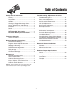
Table of Contents Troubleshooting, Adjustments & Service Troubleshooting Chart ...................................11 Drive Chain Adjustment.................................12 Skid Shoe Adjustment ...................................12 Electric Chute Rotator Gear ..........................12 Lift Rod Adjustment .......................................13 Belt Tension Adjustment ................................14 Belt Replacement ..........................................14 Safety Rules & Information Training .
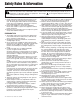
Safety Rules & Information This machine is capable to amputating hands and feet. Read these safety rules and follow them closely. Failure to obey these rules could result in loss of control of unit, severe personal injury or death to you, or bystanders, or damage to property or equipment. The triangle in text signifies important cautions or warnings which must be followed. TRAINING OPERATION 1. Read, understand, and follow all instructions on the machine and in the manuals before operating this unit.
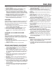
Safety Rules 8. Always follow the engine manual instructions for storage preparations before storing the unit for both short and long term periods. 9. Always follow the engine manual instructions for proper start-up procedures when returning the unit to service. 10. Maintain or replace safety and instruction labels as necessary. 11. Keep nuts and bolts tight and keep equipment in good condition. 12. Never tamper with safety devices.
Safety Decals SAFETY DECALS All DANGER, WARNING, CAUTION and instructional messages on your unit should be carefully read and obeyed. Personal bodily injury can result when these instructions are not followed. The information is for your safety and it is important! The safety decals below are on your unit. This unit has been designed and manufactured to provide you with the safety and reliability you would expect from an industry leader in outdoor power equipment manufacturing.
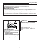
Safety Information Required Accessories It is required that tire chains and two rear wheel weights or Quick Tach Weights are used. Never operate on slopes greater than 17.6% (10°). Recommended Accessories A rear-mounted weight box can also be added for additional traction. The maximum weight added to the tractor should not exceed 35 lbs. per wheel, plus 100 additional pounds in the rear weight box. For operation on slopes greater than 15% (8.
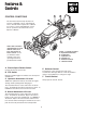
Features & Controls C CONTROL FUNCTIONS D B The information below briefly describes the function of individual controls. Operating the tractor and attachment requires the combined use of these controls and additional controls whose operation is described in the tractor Operator’s Manual. A E F Please take a moment and familiarize yourself with the name, location, and function of these controls so that you will better understand the safety and operating instructions provided in this manual. Figure 1.
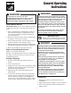
General Operating Instructions WARNING WARNING Perform the Safety System Interlock test found in your tractor Operator’s Manual. If tractor does not pass the test, do not operate the tractor. See your authorized dealer. Under no circumstances should you attempt to defeat the safety system. If auger does not start and stop when engaging/disengaging electric clutch, see your authorized dealer. Under no circumstances should you attempt to defeat the safety system.
General Operating Instructions Snow Removal Suggestions • Determine the best snow removal pattern before beginning. • Wind direction is an important factor to consider. Rotate the spout to discharge snow downwind. • Plan the pattern so that you avoid throwing snow on cleared areas and on yourself as you are operating. • When land contour permits, it is best to travel in the longest direction to minimize turning.
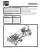
Maintenance WARNING General Lubrication Lubricate the snowthrower as shown in Figure 2. Where an oil can is shown use 30 weight oil. Where a grease gun is shown, use lithium grease. To avoid serious injury, perform maintenance on the unit only when the engine is stopped, parking brake is set and all moving parts have stopped. Always remove the ignition key before beginning maintenance or adjustments to prevent accidental starting of the engine.
Maintenance Inspect, Adjust, & Lubricate Drive Chain See Figure 3. D F G 1. Remove the two flange nuts (A) and chain guard (B). G H 2. Check the chain. Replace chain if worn or damaged. 3. There should be no slack in the chain, and the sprockets (D and E) should be aligned. The drive shaft (H) should be parallel with the auger housing. If adjustment is required proceed with steps 4 - 7. E C 4. Loosen the adjustment nuts (F). 5.
Troubleshooting, Adjustments, & Service TROUBLESHOOTING WARNING While normal care and regular maintenance will extend the life of your equipment, prolonged or constant use may eventually require that service be performed to allow it to continue operating properly. To avoid serious injury, perform maintenance on the tractor or mower only when the engine is stopped and the parking brake engaged.
Troubleshooting, Adjustments, & Service Drive Chain Adjustment See Inspect, Adjust & Lubricate Drive Chain in the MAINTENANCE Section. Skid Shoe Adjustment Loosen Nuts to Adjust On smooth surfaces such as concrete or asphalt, the scraper bar should scrape the surface. On surfaces such as gravel, the scraper bar should be set high enough so that it will not pick up debris. Figure 5. Adjusting Skid Shoes 1. Loosen the nuts securing the skid shoes (see Figure 5). 2.
Troubleshooting, Adjustments, & Service Lift Rod Adjustment C In the fully raised position the attachment should be 4”-5” off the ground. In the fully lowered position, the lift rod should compress the spring creating downward pressure on the blade. B A NOTE: Always adjust the lift height before and after adjusting the downward pressure. LIFT HEIGHT ADJUSTMENT 1. Fully raise the attachment lift. The snowthrower should be approximately 4”-5” off the ground. If not, go to step 2. 2.
Troubleshooting, Adjustments, & Service Belt Tension Adjustment See Figure 8. 1. With the snowthrower drive belt installed, trunnion (A) should be between marks (G) on spring tension bracket (B) for correct belt tension. 2. Turn belt tension handle (C) to move trunnion forward or rearward until it is between marks. 3. If trunnion cannot be placed between marks, loosen capscrew (D) and reposition idler pulley (E) as necessary. The pivot bracket (F) should be perpendicular to the hitch.
Initial Setup & Assembly 10 9 11 4 8 7 12 6 5 3 28 13 16 2 14 15 1 27 26 25 17 18 24 19 23 20 21 22 Ref Qty 1 1 2 2 3 2 4 1 5 1 6 2 7 2 8 2 9 1 10 1 11 2 12 1 13 1 14 1 Description SNOWTHROWER GUIDE, Chute, Hold-Down SCREW, Plastite DISCHARGE CHUTE ASSY.
Initial Setup & Assembly B A A D A Figure 12. Discharge Chute Motor Adjustment A. Adjustment Screws B. Plastic Cover B C Figure 11. Assemble Discharge Chute A. Plastite Screw B. Hold-Down C. Chute Ring D. reinforcement Ring Gear A E INITIAL SETUP & ASSEMBLY B F C NOTE: Some of the following setup procedures may already be completed. Install Hitch Install the sub-frame hitch. Refer to sub-frame hitch installation instructions. See also “Lift Variations... on page 22 of this manual.
Initial Setup & Assembly G G F E H F H D A C B C D A E B Figure 14. Deflector Control Cable Support Arm A. Support Arm B. 5/16-18 x 1 Capscrew C. Lockwasher & Nut D. 3/8-16 x 1-1/4 Capscrew E. Assist Lever F. Spacer G. Lockwasher & Nut H. Large Washer Figure 15. Install Power Port & Switch A. Rotator Motor Harness B. Trailer Plug C. Switch Harness Lower Plug D. Plug Hole (Frame) E. Tractor Harness Leads F. Switch Harness Upper Plug G. Switch H.
Initial Setup & Assembly Mount Remote Deflector Control 1. Using the template included in the back of this manual, drill two 9/32” holes in the dashboard to mount the remote chute control. See MOUNTING REMOTE DEFLECTOR CONTROL on page 22. 2. Mount the mounting bracket (E, Figure 16) to the dashboard. Secure with two 1/4-20 x 7/8 capscrews (A), lockwashers (C), and large flat washers (B). E D A C B Figure 16. Mount Control Bracket - Current Models A. 1/4-20 x 7/8 Capscrews D. 1/4-20 Nuts B.
Initial Setup & Assembly Install Snowthrower CONNECT TO HITCH 1. Position the snowthrower in front of the hitch. Insert the hitch pin (A, Figure 18) through the snowthrower and hitch on both sides of the snowthrower. Secure with a hair pin clip (B). Use the back set of hitch holes (see inset). B A Figure 18. Install Snowthrower A. Hitch Pin B. Hair Pin Clip INSTALL LIFT ROD B 2. Attach the front of the lift rod assembly (A, Figure 19) to the lift arm (C). Secure with a hair pin clip (B). A Figure 19.
Initial Setup & Assembly INSTALL ASSIST SPRING 4. Lift the snowthrower up fully and support with wood blocks. 5. Assemble the lift assist spring (B, Figure 21) and spring bracket (C). Install the spring assist bracket (C) in the front bumper. Be sure the spring notch is in the lower position. 6. Rotate the assist spring lever (A) backwards. Hook the spring (A) on the lever (C) and rotate the lever forwards. C B CAUTION A Spring under tension. Keep clear of pinch points. Figure 21.
Initial Setup & Assembly INSTALL DRIVE BELT B 8. Route the drive belt as shown in Figure 23. Note that the back of the belt rides in the back-side idlers (B). C B 9. With the snowthrower drive belt installed, the trunnion (A, Figure 24) should be between the marks (G) on spring tension bracket (B) for correct belt tension. Turn belt tension handle (C) to move trunnion forward or rearward until between marks.
Removal & Normal Installation A B C F E D Figure 25. Dozer Removal A. Rotator Motor Plug C. Hair Pin Clip B. Lift Rod D. Hitch Pin & Clip E. Spring Bracket F. Clevis Pin & Clip Removal 5. Disconnect the rotator motor plug (A). 1. Fully raise and support the snowthrower with wood blocks. 6. Disconnect the rear of the lift rod (B) from the lift arm extension. Remove the hair pin clip (C) from the front of the lift rod. Remove the lift rod.
Removing & Installing the Snowthrower 7. Use the trunnion handle (C, Figure 26) to relieve belt tension. Remove the belt from the snowthrower drive pulley (D, Figure 27). 8. Remove the hitch pin and clip (D, Figure 25) from the snowthrower and remove the snowthrower. Reinstall all pins and clips to prevent loss. Normal Installation 1. Install the sub-frame hitch (see hitch installation instructions). B C A G 2.
Tractor Lift Linkage Snowthrower & Dozer Applications Snowthrower & Dozer Applications E A A B F C D E C B D Mower Applications Mower Applications G A A B F G F E Figure 28. Lift Lock Plate - Hydraulic Lift Models A. Lift Cylinder B. Flat Head Pin (Original) C. Flat Head Pin (New) D. Lock Plate E. Hair Pin Clips F. Lift Shaft Assy. G. Washers C D Figure 29. Lift Link - Manual Lift Models A. Pin B. Rear Hole of Lift Bar (Snowthrower Applications) C. Spacer D. Hair Pin Clip E.
Hardware Identification & Torque Specifications Common Hardware Types Torque Specification Chart Hex Head Capscrew FOR STANDARD MACHINE HARDWARE (Tolerance ± 20%) Washer Hardware Grade Lockwasher Carriage Bolt No Marks SAE Grade 2 Hex Nut Size Of Hardware Standard Hardware Sizing 8-32 8-36 10-24 10-32 1/4-20 1/4-28 5/16-18 5/16-24 3/8-16 3/8-24 7/16-14 7/16-20 1/2-13 1/2-20 9/16-12 9/16-18 5/8-11 5/8-18 3/4-10 3/4-16 7/8-9 7/8-14 1-8 1-12 When a washer or nut is identified as 1/2”, this is the
Mounting Remote Deflector Control Line Template Up with Edge of Plastic Dashboard Mark and Drill One 9/32” Hole Mount Bracket and align with Line Mark and Drill One 9/32” Hole Figure 28. Template Location MOUNTING REMOTE DEFLECTOR CONTROL NOTE: Read through instructions before beginning. 1. Open the hood. 2. Cut out the template and place it on the lower left corner of the dashboard as shown above. E 3. Mark and drill one 9/32” hole using the template to locate the holes. 4.
Template Line Template Up with Top Crease of Plastic Dashboard Mark and Drill One 9/32” Hole Line Template Up with Edge of Plastic Dashboard 27
Template 28
MANUFACTURING, INC. 500 N Spring Street / PO Box 997 Port Washington, WI 53074-0997 www.simplicitymfg.com © Copyright 2004 Simplicity Manufacturing, Inc. All Rights Reserved. Printed in USA.